Introduction
When engineers need to transmit torque between parallel shafts without introducing axial load, spur gears are the default answer. Straight teeth machined parallel to the rotational axis generate only radial and tangential forces during operation—no thrust load—which keeps bearing selection straightforward and housing design simple.
That mechanical directness explains their presence across industrial machinery, CNC equipment, medical devices, and agricultural systems alike. Compared to helical or bevel alternatives, spur gears are easier to manufacture, easier to specify, and lower in cost without sacrificing reliability.
This guide covers the fundamentals engineers and designers need: how spur gears work, critical design parameters (module, pressure angle, face width, backlash), material and heat treatment selection, AGMA precision grades, industry applications, and how spur gears compare to helical, bevel, and worm gear alternatives.
Key Takeaways
- Spur gears feature straight teeth on cylindrical faces, operate on parallel shafts, and generate no axial thrust—making them mechanically simple and efficient
- Core design parameters: module (metric) or diametral pitch (imperial), pressure angle (20° standard), number of teeth, face width, and backlash
- Material selection depends on load, speed, environment, and precision; steel alloys dominate heavy-duty applications while plastics suit lighter, quieter uses
- AGMA precision grades run A2–A11 (lower number = tighter tolerance); high-speed or noise-sensitive applications typically require A6 or better
- Custom manufacturing and reverse engineering address non-standard specifications and obsolete equipment replacement
How Spur Gears Work
The Involute Tooth Profile
The involute curve is the standard tooth form for spur gears because it maintains a constant velocity ratio between meshing gears regardless of minor center distance variation. The involute is defined as the path traced by a point on a straight line rolling without slipping on a base circle.
When two involute spur gears mesh, the common normal to the two curves at the point of contact—the line of action—always passes through a fixed pitch point on the line of centers. This geometric property ensures smooth, predictable motion and makes manufacturing and replacement straightforward, since small variations in center distance don't alter the velocity ratio.
Meshing Action and Contact Ratio
As spur gears rotate, successive teeth engage and disengage in a continuous cycle. The contact ratio represents the average number of tooth pairs in contact simultaneously at any given moment. A contact ratio above 1.2 is the minimum threshold for smooth, evenly distributed load transmission. At exactly 1.0, one tooth leaves contact at the exact moment the next engages, causing severe impact stress and noise. AGMA recommends a minimum contact ratio of 1.2 for spur gears, with ratios between 1.3 and 1.8 considered standard practice to ensure load sharing and minimize dynamic loading.
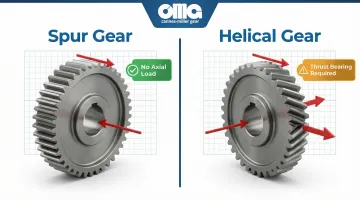
No Axial Thrust Load
Unlike helical gears, spur gear teeth are parallel to the shaft axis. This means the resultant force on mating teeth acts purely in the radial-tangential plane—there is zero axial thrust. This simplifies bearing selection (no need for thrust bearings) and reduces housing design complexity, making spur gears the preferred choice when axial load management is a design constraint.
With the load characteristics understood, the next step is calculating how gear geometry controls speed and torque.
Gear Ratio Fundamentals
Gear ratio is determined by the ratio of driven gear teeth to driver gear teeth, and directly governs two output variables:
- Output speed moves inversely with ratio — a 3:1 reduction cuts speed to one-third
- Output torque scales directly with ratio — that same 3:1 reduction triples torque (minus losses)
For example, a 20-tooth pinion driving a 60-tooth gear produces exactly that 3:1 reduction. This is the foundational calculation in any spur gear train design.
Gear ratio determines mechanical advantage, but efficiency determines how much of that power actually reaches the output shaft.
Power Transmission Efficiency
Well-manufactured spur gears achieve high transmission efficiency, but the commonly cited 98–99% per mesh is highly conditional. Transient elastohydrodynamic lubrication (EHL) models reveal that efficiency depends heavily on pitch-line velocity, applied torque, oil viscosity, and surface roughness. Total power loss breaks into two categories:
- Load-dependent (mechanical) losses — driven by rolling and sliding shear within the lubricant
- Load-independent (spin/churning) losses — present regardless of transmitted torque
For critical power-transmission calculations, don't blindly apply a 1% loss rule; use thermally coupled EHL models to account for actual operating conditions.
Key Design Parameters and Gear Terminology
Module and Diametral Pitch
Module (metric standard, measured in mm) and diametral pitch (imperial standard, teeth per inch of pitch diameter) are the fundamental tooth sizing parameters. Gears can only mesh if they share the same module or diametral pitch. The conversion formula is:
Module (mm) = 25.4 / Diametral Pitch
For example, a 2mm module gear is equivalent to a 12.7 diametral pitch gear.
Pressure Angle
The standard pressure angle is 20°, with 14.5° used only in older designs now considered obsolete for new applications. The 20° pressure angle provides a wider tooth base, resulting in higher bending strength and reduced undercutting compared to 14.5°. Pressure angle affects tooth thickness, undercutting tendency, and the balance between tooth strength and smoothness of operation. While 14.5° gears operate with less radial separating force, they suffer from significantly weaker tooth roots.
Number of Teeth and Pitch Diameter
The relationship between tooth count, module, and pitch diameter is direct: pitch diameter = module × number of teeth. There's also a critical minimum tooth count rule to avoid undercutting. For standard full-depth spur gears with a 20° pressure angle, the theoretical minimum is 17 teeth.
Fewer than 17 teeth causes undercutting during rack-generation manufacturing, which severely weakens the root. If a design requires 16 or fewer teeth, positive profile shifting (addendum modification) must be applied to restore root strength and prevent interference.
Face Width
Face width — the axial length of the gear teeth — directly affects load capacity. Wider faces distribute load over a greater contact area but increase weight and demand tighter shaft and bearing alignment.
A common starting point sets face width between 8 and 16 times the module (or 3 to 5 times the circular pitch). Treat that as a preliminary estimate only. Final face width must be validated using the AGMA Load-Distribution Factor to account for non-uniform load distribution caused by shaft deflection, bearing clearances, and mounting rigidity.
Backlash
Backlash is the intentional clearance between mating tooth flanks when gears are in mesh. It's necessary for several reasons:
- Accommodates thermal expansion during operation
- Provides space for lubrication
- Compensates for manufacturing tolerances
- Prevents binding due to deflection
Too little backlash causes binding, overheating, and premature failure. Too much backlash causes impact loading, noise, and positioning inaccuracy. Backlash is measured two ways: circular (circumferential) backlash is the arc distance measured near the reference cylinder, while normal backlash is the minimum clearance between trailing flanks measured perpendicular to the tooth surface.
Types of Spur Gears
External Spur Gears
External spur gears are the most common configuration, with teeth cut on the outer surface of the cylinder. Two external gears in mesh rotate in opposite directions. This configuration is used for speed reduction and torque multiplication across virtually every industry—from conveyor systems and pumps to CNC machine tools and automotive transmissions.
Internal Spur Gears
Internal spur gears have teeth cut on the inside of a cylindrical ring, meshing with a smaller external pinion. Unlike external gear pairs, both gears rotate in the same direction. This enables more compact drive arrangements with shorter center distances and is the foundation of planetary gear systems, where planet gears engage both an internal ring gear and a central sun gear simultaneously.
Rack and Pinion
Rack and pinion is a special case where a spur gear (pinion) meshes with a flat, linear gear (rack) to convert rotary motion into linear motion. Common applications include:
- CNC machine tool tables for precise X-Y axis positioning
- Automotive steering systems
- Linear actuators in industrial automation
Materials, Heat Treatment, and AGMA Precision Grades
Common Metallic Materials
Carbon Steel: Cost-effective and provides good strength for general industrial use. Typical surface hardness ranges from 180-400 HB (Brinell) when through-hardened. Common grades include 1045 and 1050.
Alloy Steel: Offers higher strength-to-weight ratio and better hardenability for demanding applications. When case-carburized, alloys like AISI 8620 and AISI 9310 achieve 55-64 HRC surface hardness with 30-45 HRC core hardness, delivering the optimal balance of wear resistance and impact absorption.
Stainless Steel: Provides corrosion resistance for food processing, medical, marine, or chemical environments. Typical hardness ranges from 180-400 HB through-hardened, or 600-900 HV (Vickers) when nitrided.
Non-Metallic Materials
Engineering plastics (nylon, acetal/POM) and bronze offer distinct advantages:
- Reduced weight compared to steel
- Lower noise due to vibration damping
- Self-lubrication properties (especially nylon)
- Excellent corrosion resistance
Disadvantages include lower load capacity and temperature limits (typically 80-120°C for plastics). Non-metals are typically specified for light-duty, high-cycle, low-noise requirements such as office equipment, consumer products, and precision instruments.
Heat Treatment Processes
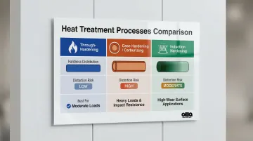
Each process trades off hardness distribution, distortion, and cost differently:
Through-hardening creates uniform hardness across the entire cross-section. It's cost-effective and works well for moderate loads, though the resulting steel is more brittle and less fracture-resistant than case-hardened alternatives.
Case hardening (carburizing) introduces carbon into the surface of low-carbon alloy steels, building a wear-resistant outer case over a tough, ductile core. The high-temperature process causes dimensional distortion, so post-process grinding is required to restore involute profile accuracy.
Induction hardening uses a copper coil to rapidly heat and quench the gear surface, producing a deep hardened case while preserving core properties. Because the entire exposed surface is hardened uniformly, selective area masking is not possible.
| Process | Hardness Distribution | Distortion Risk | Best For |
|---|---|---|---|
| Through-hardening | Uniform throughout | Low | Moderate loads, cost-sensitive |
| Case hardening | Hard case, tough core | High (grinding required) | Heavy loads, impact resistance |
| Induction hardening | Deep surface case | Moderate | High-wear, core integrity required |
Manufacturing Process and Precision
Hobbing and shaping are the standard economical processes for most industrial applications. Hobbing is a continuous generating process using a rotating cutter. Shaping uses a reciprocating pinion-like cutter, making it essential for internal gears or gears positioned close to a shoulder where hobbing can't reach.
Gear grinding removes heat treat distortion, improves surface finish, and achieves the tighter tolerances required for high-speed or low-noise applications. Carnes-Miller Gear achieves AGMA 10 precision on shaped and hobbed gears and AGMA 13 on ground spur gears, with grinding capability up to 400mm in diameter. Their in-house nital-etch testing detects grinding burns that can compromise surface integrity — a critical quality control step for any heat-treated gear.
AGMA Precision Grades Explained
The U.S. gear industry historically used ANSI/AGMA 2000-A88 (Q3 to Q15, where higher numbers = higher precision), but this was superseded by ANSI/AGMA 2015-1-A01, aligned with ISO 1328-1:2013, which reversed the scale. The current standard uses accuracy grades A2 through A11, where lower numbers indicate higher precision (smaller tolerances).
Grade Selection by Application:
- General industrial applications: AGMA grades A6-A8 (formerly Q11-Q9)
- Higher-speed or low-noise applications: AGMA grades A4-A6 (formerly Q13-Q11)
- Precision aerospace or defense applications: AGMA grades A2-A4 (formerly Q15-Q13)
The required grade depends on speed, load, noise tolerance, and operating conditions. Each grade controls specific parameters: tooth profile error, pitch error, lead deviation, and runout. Higher accuracy grades require all medium accuracy controls plus strict slope and form tolerances.
Spur Gear Applications by Industry
Industrial and Manufacturing Applications
Spur gears are the workhorse of industrial power transmission, used extensively in:
- Conveyor systems for material handling
- Pumps and compressors for fluid transfer
- Machine tools for cutting and forming operations
- Gearboxes for speed reduction and torque multiplication
Their predictability, ease of maintenance, and repairability make them the go-to choice for high-volume industrial environments. When a spur gear fails, replacement is straightforward—match the module, tooth count, and face width, and the gear can be swapped without complex realignment.
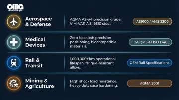
Specialized and High-Precision Sectors
That durability scales up considerably once specifications tighten. In these sectors, gear tolerances, material traceability, and compliance standards are non-negotiable:
| Sector | Key Requirement | Governing Standard |
|---|---|---|
| Aerospace & Defense | AGMA A2-A4 (ISO Class 1-4) precision; VIM-VAR AISI 9310 for fracture toughness | AS9100, AMS 2300 |
| Medical Devices | Zero-backlash positioning for surgical robotics and imaging equipment | FDA QMSR, ISO 13485:2016 |
| Rail & Transit | High durability for 1M+ km lifespans in bogie traction gearboxes | Application-specific OEM specs |
| Mining & Agriculture | Shock load resistance with reliable operation in contaminated environments | AGMA 2001, application-specific |
Selection Criteria by Application Type
Match gear specifications to application requirements by considering:
- Whether loading is constant or shock-heavy (impacts material grade and tooth geometry)
- Operating speed range — below 1,000 RPM vs. above 3,000 RPM drives tolerance class selection
- Duty cycle — intermittent use allows lighter specs than continuous 24/7 operation
- Lubrication method available: splash, spray, or oil bath each suit different enclosure designs
- Noise and vibration limits, which may push requirements toward ground tooth profiles
Spur Gears vs. Other Gear Types
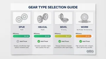
Each gear type solves a specific problem. Choosing the right one comes down to shaft orientation, load requirements, efficiency targets, and noise tolerance.
Spur vs. Helical Gears
Helical gears offer quieter operation and higher load capacity due to their angled teeth and gradual tooth engagement, but they generate axial thrust forces that require thrust bearings. Spur gears are noisier at higher speeds but mechanically simpler and less expensive.
Spur gears are the better choice when:
- Noise is not a design constraint
- Axial load management needs to stay simple
- Maximum mechanical simplicity is the priority
Spur vs. Bevel Gears
Bevel gears are used when shafts intersect at an angle (typically 90°), whereas spur gears are limited to parallel shaft arrangements. Engineers should choose bevel gears when a change of direction in the drive train is needed—for example, transferring power from a horizontal motor shaft to a vertical output shaft.
Spur vs. Worm Gears
Worm gear sets deliver very high reduction ratios (up to 360:1) in a compact footprint and offer self-locking capability when the lead angle falls below 5°. The tradeoff is efficiency: sliding tooth contact drops worm gear efficiency to 50–90%.
Spur gears are preferred when high efficiency (94–99%), reversibility, and minimal power loss matter—which explains why spur and helical configurations dominate the industrial gearbox market, projected to reach $45.5 billion by 2033.
Frequently Asked Questions
Does a smaller spur gear make it faster?
A smaller drive gear (pinion) paired with a larger driven gear increases output speed while reducing torque. Gear ratio is determined by the ratio of tooth counts—fewer teeth on the driver means a higher speed ratio at the output.
What is the best material for spur gears?
Alloy steel with case hardening (carburizing) is the most common choice for high-load industrial applications due to its strength and hardenability. Stainless steel suits corrosive environments, while engineering plastics like nylon work well for light-duty, low-noise, or self-lubricating applications.
What is the strongest type of gear?
Spiral bevel gears and heat-treated helical gears rank among the strongest due to gradual tooth engagement and higher contact ratios. For parallel shaft applications specifically, ground alloy steel spur gears at high AGMA precision grades deliver excellent load capacity and durability.
What is the difference between spur gears and helical gears?
Spur gears have straight teeth parallel to the shaft (simpler, no axial thrust, noisier at speed) while helical gears have angled teeth that engage gradually (quieter, higher load capacity, but generate axial thrust requiring thrust bearings).
What AGMA precision grade do I need for my application?
General industrial applications typically use AGMA grades A6–A8; higher-speed or low-noise applications require A4–A6; precision aerospace or defense applications may demand A2–A4. Your specific speed, load, and noise tolerance will determine the right grade.
Can spur gears be custom manufactured for non-standard specifications?
Yes, custom spur gears can be manufactured to non-standard dimensions. Experienced job shops like Carnes-Miller Gear offer reverse engineering capabilities for obsolete or discontinued gears, producing replacement parts even without original drawings by measuring and re-engineering the existing component.