Introduction
Engineers and OEM designers face relentless pressure: deliver higher torque, meet tighter noise specifications, and fit everything into smaller envelopes. In many cases, helix angle is the design lever that makes this possible.
Textbooks cover helix angle in detail, but rarely connect it to real-world outcomes — why one gear set runs quietly under load while another fails prematurely, or why two nominally identical designs perform so differently in service.
Those failures trace back to helix angle more often than most post-mortems acknowledge. Under-specified, ignored, or imprecisely manufactured — the consequences show up in noise floors, bearing loads, and service life.
What follows is a practical breakdown of how helix angle drives gear performance — and why getting it right matters well before the first tooth is cut.
Key Takeaways
- Helix angle creates gradual, overlapping tooth contact instead of the abrupt full-width engagement of spur gears
- Primary advantages: reduced noise/vibration, higher load capacity via increased effective face width, and design flexibility for compact high-torque configurations
- Angles above 20° generate significant axial thrust — account for this with appropriate thrust bearings
- Practical range for power transmission: 15°–30°; beyond this, axial load complexity outweighs capacity benefits
- Theoretical gains require tight helix angle tolerances during manufacturing to materialize
What Is Helix Angle in Gears?
Helix angle is the angle between a gear tooth's helical path and an imaginary line parallel to the gear's shaft axis. In spur gears, this angle is 0°—teeth run perfectly parallel to the shaft. In helical gears, the angle typically ranges from 1° to 44°, creating the diagonal tooth trace that defines helical geometry.
Helix angle is the mechanism designers use to control core performance variables within a given physical envelope:
- Contact ratio — more teeth in simultaneous mesh means smoother load transfer
- Load distribution — diagonal engagement spreads force along the full tooth face
- Noise behavior — gradual contact initiation reduces impact-driven vibration
- Torque capacity — increased effective face width raises the load the gear can carry
It governs how tooth contact initiates, progresses across the face width, and disengages—fundamentally changing gear performance compared to spur gears.
Helix angle is the defining geometric feature that separates helical gears from spur gears—and the primary variable designers adjust to hit specific performance targets.
Key Advantages of Helix Angle in Gear Design
Each advantage below connects directly to outcomes engineers and procurement teams track: system noise levels, gear train reliability, service life, and whether a design meets torque requirements without upsizing. Each advantage below connects directly to outcomes engineers and procurement teams track: system noise levels, gear train reliability, service life, and whether a design meets torque requirements without upsizing. These three advantages build on each other — quieter operation leads to longer tooth life, higher load capacity enables power-dense designs, and design flexibility closes the loop by fitting more performance into the same envelope.
Advantage 1: Smoother Tooth Engagement and Reduced Noise
Unlike spur gears where the full tooth width contacts instantaneously, helical gear teeth enter contact at one point and gradually sweep across the face width. This progressive engagement creates continuous, overlapping contact throughout the mesh cycle.
How this works in practice:
- Overlapping contact means multiple teeth share the load at any moment
- No sudden shock loading as teeth engage or disengage
- Overlapping contact directly reduces the impulse forces that generate noise and vibration
Real-world impact:
An SAE study on commercial gearboxes demonstrated that converting standard spur gears to helical gears yielded a 6 to 6.5 dB reduction in sound pressure levels. In aerospace applications, NASA gear-noise testing confirmed helical gears are consistently quieter than equivalent spur gears.
Why this advantage matters:
- Gear whine is one of the most cited driver complaints in automotive gearboxes
- Reduced vibration means lower fatigue loading on tooth flanks, housings, and bearings—extending service life
- In aerospace actuators, medical equipment, and precision industrial drives, low noise is a functional requirement, not just comfort
KPIs impacted:
- Acoustic emission levels (dB)
- Vibration amplitude
- Tooth and bearing fatigue life
- Maintenance interval length
When this advantage matters most:
High-speed applications where mesh frequency is audible or resonant; applications with strict noise/vibration specifications (aerospace, medical, automotive); systems where vibration-induced fatigue is a failure mode.
Advantage 2: Higher Load Capacity and Torque Transmission
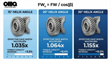
Helix angle increases a gear's effective face width beyond its physical dimension. The formula: FWₑ = FW / cos(β), where FW is physical face width and β is helix angle.
This means a helical gear carries load across a longer tooth engagement path than a spur gear of identical physical dimensions.
Load capacity gains by helix angle:
| Helix Angle | Effective Face Width Multiplier | Torque Capacity Increase |
|---|---|---|
| 15° | 1.035x | +3.5% |
| 20° | 1.064x | +6.4% |
| 30° | 1.155x | +15.5% |
Real-world impact:
For applications running near torque limits of an existing spur gear design, converting to a helical gear with even a modest 15°–20° helix angle reclaims load capacity within the same housing footprint. At 30°, effective face width increases approximately 15.5% compared to physical width.
Why this matters for gear selection:
- Avoid upsizing gear train or housing (reduces cost and weight)
- Under-designed gear trains in demanding duty cycles lead to premature failure
- Enables high-power-density configurations in constrained envelopes
KPIs impacted:
- Torque rating and load capacity
- Power density
- Gear train service life
- System weight
- Component replacement frequency
When this advantage matters most:
High-torque applications — mining equipment, rail drives, agricultural machinery, construction equipment — where increasing physical gear size is constrained by envelope or weight budgets.
Advantage 3: Design Flexibility for Compact, High-Performance Configurations
Higher load capacity per unit of physical face width means engineers can achieve equivalent torque transmission with gears that have smaller diameters, fewer teeth, or shorter face widths than spur gear counterparts while maintaining the same durability ratings.
In practice, this lets system designers reduce gear train weight, shrink center distances, or fit higher-torque gearing into housings originally built for spur gears. Specifying transverse-pitch helical gears preserves center distance compatibility with existing spur gear layouts — a critical consideration in retrofit projects.
Proven weight savings:
The Sikorsky Advanced Rotorcraft Transmission (ART) program used a split-path configuration with a double-helical output stage, achieving:
- 23% overall weight reduction (10,795 lbs to 8,287 lbs)
- 390% increase in reliability (997 hours to 3,890 hours MTBR)
- >10 dB noise reduction in cabin environment
Additional flexibility:
By selecting left-hand or right-hand helix combinations, designers manage thrust force direction to work with existing bearing arrangements, giving designers direct control over thrust load direction within the existing bearing arrangement.
KPIs impacted:
- System weight
- Housing/envelope dimensions
- Center distance
- Material cost per gear
- Power-to-weight ratio
When this advantage matters most:
Aerospace and defense applications with strict weight and volume constraints; machine tool spindles; transportation drivetrain redesigns; retrofit projects replacing spur gears in existing housings.
What Happens When Helix Angle Is Ignored or Poorly Specified
Ignoring helix angle—or specifying it without tracking its full design implications—leads to predictable, avoidable failures:
Common failure modes:
- Excessive noise and vibration in high-speed applications, typically the first sign that spur gears were used where helical gears were required
- Premature tooth wear or fatigue when load capacity is overestimated for spur gears running high-torque duty cycles
- Bearing failures from unaccounted axial thrust loads—specifying a helix angle without carrying the thrust implications through to bearing selection
- Contact pattern shifts and uneven load distribution when helix angle tolerances aren't held during production, eliminating every theoretical advantage
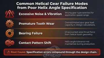
Each of these failures traces back to the same root cause: specification errors compound through the design chain.
Why precision matters:
Research shows that poor lead and helix angle specification causes severe edge contact, shifting load distribution to face width extremities. This localized overloading increases tooth root bending stress sharply, leading to rapid pitting and catastrophic tooth breakage.
Precision gear manufacturing standards like AGMA quality ratings exist to prevent exactly this. Achieving AGMA Q12 or higher requires gear grinding—hobbing or shaping alone won't get you there.
How to Get the Most Value from Your Gear's Helix Angle
Helix angle advantages are only realized when three things align: the right angle is selected for the application, the full system effects (especially axial thrust) are designed for, and the gear is manufactured to required precision.
Angle Selection Guidance
For general power transmission, helix angles of 15°–30° strike the best balance between load capacity gains and manageable axial thrust.
- Angles under 15°: Provide minimal contact ratio improvement
- Angles above 30°: Generate thrust loads requiring more robust bearing arrangements, adding cost
- At 45°: Gears become crossed helical (screw gears) with very different mesh behavior
Managing Axial Thrust
Helix angle creates an axial (thrust) force proportional to transmitted torque: Fₐ = Fₜ × tan(β)
Thrust force as percentage of tangential load:
| Helix Angle | Axial Thrust (% of Tangential Load) |
|---|---|
| 15° | 26.8% |
| 20° | 36.4% |
| 30° | 57.7% |
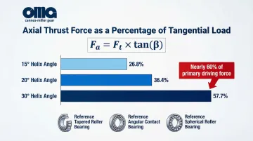
At 30°, support bearings and housing must absorb an axial force equal to nearly 60% of the primary driving force. This requires:
- Tapered roller bearings for high radial and axial loads
- Angular contact ball bearings for moderate axial loads at higher speeds
- Spherical roller thrust bearings for very high axial loads with misalignment
Manufacturing Precision Requirements
The helix angle must be consistently held across the full face width and from part to part in production. Gear grinding—beyond hobbing or shaping alone—delivers the tight tolerances high-performance helical gears require.
Carnes-Miller Gear's in-house gear grinding (up to 400mm diameter, AGMA 13 quality on heat-treated helical gears) finishes helical gears to the precision needed to fully realize the noise, load, and life advantages the helix angle is designed to deliver—including lead, profile, and tip relief modifications per customer specifications.
Conclusion
Helix angle is the geometric parameter that determines whether a gear set delivers smooth, quiet, reliable power transfer—or falls short on noise, load capacity, and service life.
Those performance gains depend on three interdependent factors:
- Correct angle selection for the load, speed, and noise requirements
- System design that accounts for and manages axial thrust
- Manufacturing precision that holds tight angular tolerances consistently
Each element depends on the others. Miss one, and the benefits of the other two are compromised.
For engineers specifying helical gears across demanding sectors—aerospace, defense, mining, industrial—the manufacturing partner is as consequential as the design itself. Carnes-Miller Gear has produced precision helical gears for these sectors since 1973, with in-house grinding capability up to 400mm and AGMA 13-rated ground gears. That level of angular accuracy is what separates a gear that performs to spec from one that fails prematurely in the field.
Frequently Asked Questions
What is the effect of helix angle on a helical gear?
Increasing the helix angle raises the contact ratio (more teeth share load simultaneously), increases effective face width for higher torque capacity, reduces noise and vibration, and generates axial thrust force proportional to the angle.
What is the best helix angle for helical gears?
For most power transmission applications, 15°–30° is the practical optimum—balancing meaningful load capacity and noise benefits against manageable axial thrust loads. The specific best angle depends on speed, torque, noise requirements, and available bearing support.
What happens to the load capacity of helical gears with helix angles greater than 20 degrees?
Load capacity continues to increase as helix angle rises above 20°, due to further effective face width gains. However, axial thrust loads also increase significantly, requiring heavier-duty thrust bearings. Beyond roughly 30°–35°, bearing and housing complexity typically outweighs the load capacity benefit in most standard applications.
How does helix angle affect noise and vibration in a gear system?
A higher helix angle produces more gradual tooth engagement and a higher contact ratio, which distributes impact forces over time and across multiple teeth. This directly reduces mesh noise, vibration amplitude, and the risk of resonance in the gear housing.
What is the difference between normal pitch and transverse pitch helical gears?
Normal pitch gears are measured perpendicular to the tooth flank, resulting in a larger center distance than an equivalent spur gear. Transverse pitch gears are measured along the shaft axis and maintain the same center distance as a comparable spur gear, making them the preferred choice for direct spur gear replacements.
How does helix angle impact thrust bearing selection?
Helix angle creates an axial (thrust) force proportional to the transmitted torque and the tangent of the helix angle. Designers must select thrust bearings rated to absorb this load, and the direction of thrust depends on the hand (left or right) of the helix and the direction of rotation.