Introduction
Spur gears are the most widely used gear type in mechanical power transmission—found in everything from medical devices to mining equipment—yet proper specification is far more demanding than their simple geometry implies. Straight teeth and a cylindrical profile are straightforward to visualize; getting them right requires careful control of AGMA quality grades, material selection, heat treatment, and post-processing. A single misstep in any of these areas can mean premature failure, excessive noise, or unplanned downtime in critical applications.
This article covers how spur gears work, what drives their performance, the industries that depend on them, and why manufacturing precision—AGMA quality grades, grinding processes, heat treatment controls—determines whether a gear succeeds or fails in service.
Whether you're an OEM engineer specifying gears for aerospace assemblies or a maintenance manager sourcing replacements for heavy industrial equipment, the fundamentals here will sharpen how you evaluate cost, performance, and reliability tradeoffs.
TLDR:
- Spur gears achieve 95–99% per-mesh efficiency and generate zero axial thrust, simplifying drivetrain design
- AGMA quality grades range from 10 (hobbed/shaped) to 13 (ground), setting dimensional precision requirements by application
- Post-heat-treatment grinding corrects thermal distortion while preserving hardness benefits
- Nital-etch testing detects grinding burns that can reduce fatigue life by over 80%
- Material and process choices drive gear performance, noise behavior, and expected service life
What Are Spur Gears and How Do They Work
Anatomy of a Spur Gear
Spur gears feature a cylindrical blank with straight teeth cut parallel to the gear axis. Their involute tooth profile ensures a constant velocity ratio throughout the mesh cycle—a critical factor for applications requiring precise, predictable motion. When involute surfaces roll and slide against each other, they produce consistent angular velocity because the line of action remains normal to the contacting surfaces throughout engagement.
Key design parameters every engineer and buyer must understand:
- Module (metric) vs. Diametral Pitch (inch system): Module is the ratio of pitch diameter in millimeters to the number of teeth; DP is the ratio of teeth to pitch diameter in inches. These systems are not interchangeable—mating gears must share the same module or DP.
- Pressure angle: The 20° pressure angle is the current global standard, producing thicker, stronger tooth bases with higher load capacity and better resistance to undercutting (especially on pinions with fewer than 17 teeth). The legacy 14.5° pressure angle, once favored for quieter operation, is now obsolescent but remains common in replacement parts for older machinery.
- Pitch diameter: The theoretical diameter where tooth contact occurs
- Backlash: The clearance between mating teeth, essential for lubrication and thermal expansion
Mating gears must share identical module or DP values — a module 2.5 gear cannot mesh with a module 3.0 gear, regardless of tooth count or any other parameter.
How Tooth Engagement Transfers Torque
As the driving gear rotates, its teeth push against the driven gear along the pitch circle, transmitting torque from one parallel shaft to another. The practical consequence of straight-tooth geometry is significant: spur gears generate radial forces only, with no axial thrust. This simplifies bearing selection and housing design compared to helical gears, which require thrust bearings to handle axial loads.
For engineers specifying drivetrain components, that distinction has real cost implications:
- Standard ball bearings suffice — no thrust-rated bearings required
- Mounting arrangements are straightforward and lighter
- Housing designs stay simpler, reducing machining and assembly costs
These characteristics make spur gears the default choice when parallel-shaft power transmission is involved and axial space is at a premium.
Key Performance Characteristics of Spur Gears
Transmission Efficiency and Power Density
Properly lubricated spur gear pairs achieve 94–99% efficiency per mesh stage, matching helical gears and far outperforming worm gears (which typically reach only 30–90% due to high sliding friction). Direct tooth engagement and minimal sliding friction make spur gears well-suited for multi-stage gearboxes where cumulative losses compound across each mesh.
Torque capacity scales from miniature instrument gears to large industrial drives. Engineers adjust module size, tooth count, face width, and material to span that range—covering everything from micro-module gears in medical devices to large-module, wide-face gears handling shock loads in mining equipment.
No Axial Thrust: A Structural Advantage
The absence of axial force generation directly reduces cost and complexity. While helical gears require thrust bearings to manage axial loads generated by their angled teeth, spur gears need only radial bearings. For system designers, this means:
- Lower bearing costs
- Simpler housing designs
- Reduced mounting complexity
- Lighter overall drivetrain weight
- Easier maintenance and replacement
Load Capacity, Contact Stress, and Contact Ratio
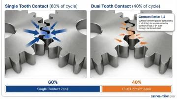
Standard spur gears operate with a transverse contact ratio between 1.2 and 1.6. A contact ratio of 1.4 means that for 40% of the mesh cycle, two pairs of teeth share the load, while for the remaining 60%, only one pair carries the full load. This abrupt load alternation between one and two tooth pairs creates transmission error—the primary driver of gear noise and vibration.
Helical gears achieve higher total contact ratios because their angled teeth engage gradually across the face width, adding an axial overlap component. For spur gears, proper sizing, material selection, and surface hardening compensate for the lower contact ratio—surface-hardened teeth can increase allowable contact stress by 2–3× compared to through-hardened alternatives, enabling adequate load capacity across demanding applications.
Noise and Vibration: The Inherent Trade-Off
Spur gears produce more vibration and noise at high speeds than helical gears because their straight teeth engage abruptly—one full tooth pair at a time. This full-line simultaneous engagement creates transmission error that acts as the primary excitation mechanism for gear noise.
This is inherent to straight-tooth geometry, not a manufacturing defect. However, noise can be substantially reduced through:
- Tighter AGMA quality grades (ground gears with AGMA 13 vs. hobbed gears with AGMA 10)
- Correct backlash control
- Proper lubrication to dampen impact forces
- Appropriate speed selection—keeping tip speeds within recommended ranges
Higher AGMA quality grades define tighter tolerances for tooth spacing, profile, and lead, which reduces transmission error and the associated dynamic factor.
Understanding these trade-offs makes the spur vs. helical decision straightforward once operating priorities are clear.
When Spur Gears Beat Helical Gears—and When They Don't
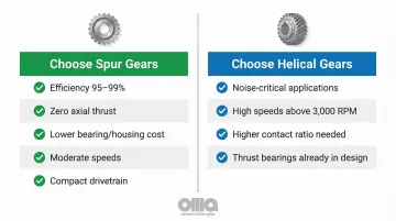
Choose spur gears when:
- Efficiency is paramount (95–99% vs. helical's 94–98%)
- Parallel-shaft applications with zero axial thrust requirement
- Cost is a primary concern (simpler manufacturing, lower bearing costs)
- Moderate speeds and reasonable noise tolerance
- Gearbox space and weight constraints favor a compact, simpler drivetrain
Choose helical gears when:
- Noise minimization is critical (automotive transmissions, HVAC systems)
- High speeds demand smoother engagement
- Loads require higher contact ratios for better load distribution
- Thrust bearings are already part of the design and axial load is manageable
In practice, most industrial and OEM applications favor spur gears for their efficiency and cost profile—noise concerns are addressed through AGMA quality upgrades rather than switching gear type entirely.
Spur Gear Applications Across Industries
Industrial Machinery and General Manufacturing
The global industrial gearbox market reached $31.9 billion in 2025, with spur gears ubiquitous throughout this sector. Core applications include:
- Drive conveyor systems with reliable, efficient power transmission for material handling
- Step down motor speed in reducers using multiple gear pairs in series, multiplying torque across synchronized shafts
- Create positive displacement in gear pumps for hydraulic and lubrication systems
- Enable accurate spindle speed control and feed rates in machine tools
- Maintain precise registration and timing in synchronized printing machinery trains
High reduction ratios through multiple stages are why speed reducers remain one of the most common spur gear applications across industrial facilities.
Specialized High-Precision Sectors
Aerospace, defense, and medical applications impose requirements that distinguish them from standard industrial use:
- Tighter dimensional tolerances — AGMA 12–13 grades vs. AGMA 8–10 for general industrial use
- Documented heat lot traceability and material test reports for every component
- Certified heat treatment processes with documented case depth and hardness profiles
- Full traceability per AS9100D for aerospace and ISO 13485:2016 for medical devices
In high-end testing equipment and defense systems, gear assemblies must meet repeatable positioning standards that demand the highest precision manufacturing. Carnes-Miller Gear has manufactured special gear assemblies for high-end testing of specialized equipment, achieving AGMA 13 quality ratings on ground spur gears to meet these demanding specifications.
Heavy-Duty and Outdoor Industries
Mining, construction, agricultural, and rail applications present demanding environments where spur gears must withstand:
- Absorb sudden torque spikes from impacts, hard starts, and stops
- Resist contamination from dirt, dust, moisture, and corrosive chemicals
- Perform across wide temperature ranges, from sub-zero cold starts to sustained high heat
- Endure millions of load cycles under continuous heavy cycling without failure
In these contexts, material selection, heat treatment depth, and surface hardness become the primary engineering decisions. Case-hardened alloy steels like AISI 8620 provide the ideal combination: a hard, wear-resistant surface (55–60 HRC) to resist macropitting, with a tough, ductile core to absorb shock loads and resist bending fatigue.
Critical Manufacturing Processes: From Hobbing to Gear Grinding
Gear Hobbing and Gear Shaping: Establishing Tooth Form
Two primary processes establish the tooth profile before heat treatment:
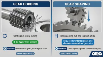
Gear hobbing is a continuous, rotary cutting process ideal for external spur gears in volume production. The hob (a cylindrical cutter with helical cutting teeth) rotates in sync with the gear blank, progressively generating the involute tooth form. Hobbing is 3 to 5 times faster than shaping, making it the most productive and economical method for external gears with no shoulder interference.
Gear shaping uses a reciprocating pinion-shaped cutter that meshes with the gear blank, cutting one tooth space at a time. This process is essential for internal gears and gears positioned close to shoulders or flanges where hobbing tools cannot reach. While slower than hobbing, shaping is mandatory when geometric constraints prevent hob tool clearance.
Both processes establish tooth profile and pitch accuracy, with the resulting AGMA quality grade reflecting how precisely the process is controlled. Typical pre-grind quality ranges from AGMA A4–A8 (ISO 5–9) for both methods.
Why Gear Grinding Is Required After Heat Treatment
Heat treatment—carburizing, case hardening, induction hardening—introduces thermal distortion that shifts tooth geometry out of specification. Quenching the through-heated gear causes phase transformations that introduce dimensional distortion, warping the involute profile, lead, and pitch spacing.
Gear grinding, as a post-heat-treatment process, restores dimensional accuracy while preserving the metallurgical benefits of hardening. Precision grinding removes small amounts of material to restore precise involute geometry, correct runout, and enable micro-geometry modifications like tip relief.
Without grinding after heat treatment, a gear may have the correct hardness but incorrect geometry, leading to uneven load distribution, high contact stresses on individual teeth, and premature failure. This is why high-precision applications mandate ground gears—the grinding step is what transforms a heat-treated blank into a precision component.
Surface Finish and Its Impact on Performance
Surface finish (Ra value) on tooth flanks directly affects:
- Smoother flanks reduce impact forces and audible noise during tooth engagement
- Finer finishes support thinner, more consistent lubrication films
- Lower surface roughness minimizes stress concentrations and extends contact fatigue life
Typical surface finish capabilities:
- Ground gears: Ra 0.03 µm to 1.1 µm (depending on grit size and wheel speed)
- Hobbed gears: Ra 0.8 µm to 1.6 µm
- Shaped gears: Ra 0.6 µm to 1.2 µm
Applications with noise constraints or high-cycle fatigue requirements specify ground gears specifically for this superior surface finish. Carnes-Miller Gear's grinding capability extends to 400mm (15.75 inches) diameter, serving heavy industrial and specialized sector requirements with AGMA 13 quality on ground spur gears.
In-House Nital-Etch Testing: Catching Grinding Burns Before They Ship
Grinding burns are localized thermal damage to the surface layer of a gear tooth caused by excessive heat during grinding.
When the surface is heated past the austenitizing temperature and rapidly quenched by coolant, it creates a brittle "white layer" of untempered martensite (re-hardening burn) over softer, over-tempered martensite (tempering burn).
The impact is severe: grinding burns replace beneficial compressive residual stresses with detrimental tensile residual stresses, reducing pitting fatigue life by over 80%—from 38.8 million cycles (undamaged reference) to just 3.3 million cycles in controlled testing.
Nital-etch testing per ISO 14104:2017 and SAE AMS2649E is the industry-standard non-destructive method for detecting these invisible defects. The process uses dilute nitric acid to exploit differential dissolution, creating visual contrast between healthy tempered martensite and thermally damaged microstructures.
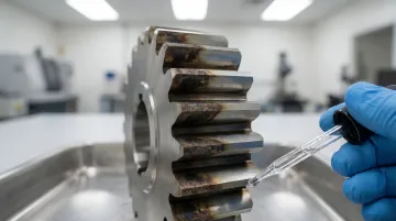
Carnes-Miller Gear performs in-house nital-etch testing as part of its quality control process—a critical safeguard for applications in aerospace, defense, and medical sectors where subsurface damage is unacceptable.
Reverse Engineering and Salvage Capabilities
For OEM customers needing to replace gears from obsolete equipment where no original drawings exist, reverse engineering from the worn gear itself is possible. The process extracts:
- Tooth count and module/DP
- Pressure angle (20° or legacy 14.5°)
- Face width and overall dimensions
- Bore diameter and keyway specifications
- Hub geometry and mounting features
Carnes-Miller Gear's 50+ years of experience enables this process across spur, helical, worm, and planetary gear types.
The company can also salvage gears that have experienced heat treat distortion through precision grinding, rather than scrapping and remaking them. This is a cost-effective alternative when distortion falls within correctable limits.
AGMA Quality Standards: What They Mean for Your Application
Understanding AGMA Quality Grades
The current primary standard for spur gear accuracy is ANSI/AGMA 2015-1-A01, which officially replaced the legacy ANSI/AGMA 2000-A88 standard. Critical change: To align with ISO 1328-1 global standards, AGMA 2015-1-A01 reversed the numbering system. Under the old system (Q3 to Q15), higher numbers indicated higher precision. Under the current system (A2 to A11), lower numbers indicate higher precision.
This inversion creates a serious procurement risk: Specifying an "AGMA 10" under the new standard will result in a low-quality commercial gear, whereas under the old standard, it denoted a high-precision component. Engineering and procurement teams must immediately audit legacy drawings to verify which standard is referenced.
AGMA quality grades define a numerical scale with tighter tolerances applied to:
- Single pitch deviation
- Total pitch deviation
- Total profile deviation
- Total helix (lead) deviation
Smaller allowable deviations in each of these parameters translate directly to quieter operation, better load distribution, and longer service life.
Grade Requirements by Application Type
Practical guidance on grade selection:
| Application Type | AGMA 2015-1-A01 Grade | Legacy 2000-A88 Equivalent | Typical Manufacturing Method |
|---|---|---|---|
| General Industrial / Agricultural | A8 – A11 | Q5 – Q7 | Hobbed or shaped |
| Precision Industrial / Automotive | A6 – A8 | Q8 – Q10 | Hobbed or shaped with tighter process control |
| Aerospace / Medical / High-Speed | A2 – A5 | Q11 – Q15 | Ground after heat treatment |
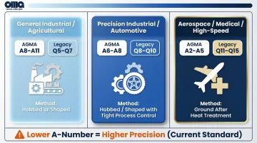
The table above uses current A-number grades throughout. If your drawings reference Q-numbers, use the legacy column to find the equivalent — and note this on updated specifications to prevent future ambiguity.
CMG's Achieved Quality Ratings
Carnes-Miller Gear achieves the following ratings under the legacy ANSI/AGMA 2000-A88 standard (the basis most customers still reference on existing drawings):
- Q10 (≈ A6 current standard) on shaped and hobbed spur gears
- Q13 (≈ A3 current standard) on ground spur gears and heat-treated gears
In practical terms, a Q13/A3 ground spur gear from CMG delivers the dimensional precision required for the most demanding aerospace, defense, and medical applications. This capability is supported by in-house grinding up to 400mm diameter, nital-etch testing for grinding burn detection, and comprehensive process validation through Gear Charts.
Reaching Q13/A3 precision requires grinding after heat treatment — not just tighter hobbing tolerances. Manufacturers without in-house grinding capability cannot reliably achieve it.
The Cost-Quality Trade-Off: Specifying the Right Grade
Match AGMA grade to application requirements. Over-specifying adds cost without functional benefit — a Q13/A3 ground gear typically costs 40–60% more than a Q10/A6 hobbed gear, with no advantage in a general industrial drive train. Under-specifying in safety-critical applications is the more serious risk: premature failure, warranty claims, and potential liability.
Frame this as a conversation to have with your gear manufacturer during specification: Explain your operating conditions (speed, load, duty cycle, noise constraints, environment) and let the manufacturer recommend the appropriate grade based on proven experience in similar applications.
Material Selection and Heat Treatment for Spur Gears
Common Material Choices and Their Trade-Offs
| Material | Common Grades | Best For | Key Trade-Off |
|---|---|---|---|
| Alloy steel | 4140, 4340, 8620 | Industrial and heavy-duty applications; AISI 8620 achieves 55–60 HRC case hardness with a tough core | Requires post-heat-treatment grinding to maintain geometry |
| Stainless steel | 316, 410 | Food processing, medical, pharmaceutical, marine environments | Lower strength than alloy steel; higher material cost |
| Aluminum alloy | 6061, 7075 | Aerospace and robotics where weight matters | Significantly lower load capacity; light-duty only |
| Engineering plastics | POM, PEEK | Medical devices, quiet light-duty applications; self-lubricating | Temperature limitations; susceptible to creep under sustained load |
Heat Treatment: Case Hardening vs. Through Hardening
Case hardening (carburizing) creates a hard, wear-resistant outer layer with a tough, shock-absorbing core. This is preferred for gears subject to contact fatigue and impact loads because the hard surface resists macropitting while the ductile core prevents brittle fracture under shock loads.
Through hardening produces uniform hardness throughout the part—simpler and less expensive, but can result in a more brittle component. Suitable for gears with lower shock loads and where surface hardness is the primary requirement.
Contact stresses peak at the surface; bending stresses peak at the tooth root. Case hardening addresses both zones simultaneously, which is why it's the default choice for high-cycle, high-load applications.
How Material and Heat Treatment Decisions Connect to Manufacturing Process
Material and heat treatment choices directly determine necessary manufacturing steps. For case-hardened alloy steel gears, each decision triggers the next:
- Case harden the gear to achieve surface hardness (55–60 HRC)
- Grind to correct thermal distortion introduced during heat treatment
- Nital-etch inspect to verify grind quality and detect grinding burns
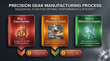
Skipping any step breaks the chain. Specifying case hardening without post-treatment grinding produces a gear with the right hardness but degraded geometry — and that combination accelerates failure faster than an unhardened gear running in spec.
Frequently Asked Questions
What is the difference between a hobbed/shaped spur gear and a ground spur gear?
Hobbed and shaped gears are produced by cutting processes that deliver functional accuracy in the AGMA 8–10 range. Ground gears undergo an additional abrasive finishing step after heat treatment that restores and tightens dimensional accuracy to AGMA 12–13 levels—required for high-precision, high-speed, or safety-critical applications where tighter tolerances directly affect performance and service life.
What AGMA quality grade do I need for my application?
Match grade to duty: AGMA 6–8 for general industrial applications with moderate speeds and loads; AGMA 10 for precision industrial equipment where noise and accuracy matter; AGMA 12–13 for aerospace, defense, medical, or high-speed precision systems where dimensional accuracy is critical.
How does heat treatment affect spur gear dimensional accuracy?
Heat treatment introduces thermal distortion that shifts tooth geometry out of specification—warping the involute profile, lead, and pitch spacing. Gear grinding is the standard corrective process to restore accuracy while retaining the hardness benefits of heat treatment. Without post-heat-treatment grinding, gears may have correct hardness but incorrect geometry, leading to uneven load distribution and premature failure.
What causes spur gear noise and how can it be reduced?
Noise stems from abrupt, full-line tooth engagement inherent to straight-tooth geometry. Reduction strategies include tighter AGMA tolerances (ground gears vs. hobbed), proper backlash control (typically 0.003–0.008 inches for industrial applications), correct lubrication to dampen impact forces, and operating within appropriate speed ranges where tip speeds remain below critical thresholds.
Can spur gears be used in aerospace and defense applications?
Yes—when manufactured to high AGMA grades (12–13), from certified alloy steels with documented material traceability, with post-grind inspection including nital-etch testing, spur gears are fully qualified for aerospace, defense, and medical applications. The key is matching manufacturing precision and quality controls to application requirements, not the gear type itself.
When should I choose a helical gear over a spur gear?
Choose helical gears when noise minimization is critical, speeds exceed 3,000 RPM, or loads require a higher contact ratio. For most parallel-shaft industrial applications, spur gears offer better efficiency (95–99% vs. 94–98%), lower cost, and simpler drivetrain design—no thrust bearings required.
Every specification decision—AGMA grade, material, heat treatment, grinding, inspection—directly affects the next. Cutting corners at any stage compromises the final result, whether you're building aerospace assemblies to AGMA 13 or industrial conveyors to AGMA 10.
For custom spur gear manufacturing with AGMA 10 on hobbed and shaped gears, AGMA 13 on ground gears, and in-house nital-etch testing, contact Carnes-Miller Gear at 704-888-4448 or visit cmgear.us.