
Introduction
Manufacturing and assembly tolerances, shaft deflections under load, and thermal expansion create inevitable misalignments in gear systems—often totaling 0.002" to 0.004" in typical industrial applications.
Without proper compensation, these misalignments concentrate loads at tooth edges, creating stress peaks 3-5x higher than center stresses and triggering rapid pitting, spalling, and premature failure.
Gear crowning—the deliberate removal of material from tooth flanks to create center contact—transforms this failure risk into controlled load distribution. Understanding when to specify crowning, which type to apply (lead vs. profile), and how much to remove is essential for preventing edge loading, reducing operational noise by up to 20 dB, and compensating for the deflections and tolerances inherent in real-world power transmission systems.
Key Takeaways
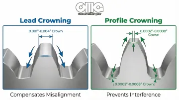
- Convex tooth surface concentrates contact at center, preventing edge stress
- Lead crowning (0.0005"-0.004" typical) compensates for shaft deflection and misalignment along the face width
- Profile crowning (0.0002"-0.0008" typical) prevents tip/root interference along the tooth height
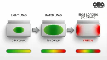
- Load spreads across 60-80% of face width under rated load when properly crowned
- Under-crowning causes edge loading; over-crowning reduces load capacity
What Gear Crowning Represents in Gear Systems
Gear crowning is the intentional removal of material from gear tooth flanks to create a convex surface. Instead of full-face contact or dangerous edge contact, crowned teeth make center contact that spreads predictably under load.
Crowning functions as both:
- Design parameter specified during initial gear design to account for known deflections
- Corrective measure applied to compensate for manufacturing limitations, housing distortions, or unexpected misalignments
This is a geometric modification manufactured into the tooth form through cutting, grinding, or shaving operations—not a surface treatment or coating. The crown must be precisely controlled during tooth generation or finishing to achieve the intended contact pattern.
While precision manufacturing establishes the baseline tooth geometry, real-world operating conditions introduce deflections that shift contact patterns toward tooth edges—the exact problem crowning addresses.
Factors That Influence Crowning Requirements in Real-World Operation
Manufacturing Tolerances
Even before load is applied, manufacturing processes introduce baseline errors:
- Bore parallelism tolerances (typically 0.005") and runout (AGMA Q9 runout of 0.002") create inherent misalignment
- Lead slope errors from tooth cutting (AGMA Q9 lead error ~0.0005") act as effective misalignment
- Heat treatment distortion alters tooth geometry unpredictably, requiring post-grind crowning correction
Operating Loads
System deflections under torque change alignment dynamically:
- Shaft bending creates angular misalignment proportional to shaft length and stiffness
- Bearing displacement and housing distortion contribute approximately 0.0006 in/in to misalignment slope in typical industrial gearboxes
- Combined deflections in helical gear pairs with 1.25" face width often total 0.002"-0.003" across the face
Thermal Expansion
Temperature gradients during operation shift contact patterns:
- Temperature differentials between bearings (e.g., 50°F gradient) induce misalignments of approximately 0.00025 in/in
- Uneven heating across the face width shifts the contact pattern toward cooler regions
Wear and Aging
Over service life, wear progressively alters the geometric relationships:
- Bearing wear increases clearances and allows greater shaft displacement
- Housing settling and foundation shifts alter the geometric relationship between mating gears

Types and Range of Gear Crowning
Crowning is not a single modification but encompasses different types applied to different tooth surfaces, each addressing specific contact problems.
Lead (Longitudinal) Crowning
Lead crowning removes material along the face width, creating a barrel-shaped tooth in the lengthwise direction. This is the primary modification for compensating shaft deflection and angular misalignment.
Typical lead crown amounts by application:
| Application Type | Total Crown Range | Typical Conditions |
|---|---|---|
| Light industrial gears | 0.0005"-0.001" | Lightly loaded, rigid shafts |
| Medium-duty gears | 0.001"-0.002" | Moderate loads, standard shaft stiffness |
| Heavily loaded or flexible-shaft applications | 0.002"-0.004" | High torque, long spans, cantilevered shafts |
Design rule: Lead crown magnitude should be approximately 1/2 to 1/3 of expected misalignment across the face width to effectively shift peak loads away from edges.
Profile crowning removes material along the tooth height, creating slight relief toward the tip and root. This modification prevents interference as teeth enter and exit the mesh.
Because tooth height is much shorter than face width, profile crowning uses smaller amounts:
- Precision gears: 0.0002"-0.0008" total crown
- Typical profile crowns are 1/3 to 1/5 the magnitude of lead crowns
Profile crowning is often combined with tip relief—a linear or curved removal of material near the tooth tip—to prevent impact loading as teeth enter the mesh. ISO 1328-1 defines profile crowning as a single parabolic curve where maximum material removal occurs at both tip and root.
Combined Crowning and Tolerance Specifications
Many precision gears use both lead and profile crowning simultaneously to optimize contact under multiple operating conditions—compensating for both misalignment (lead) and engagement interference (profile).
Crown tolerances are specified as a range rather than a single value:
- Example: 0.0010"-0.0020" crown allows manufacturing variation while maintaining function
- High-precision applications (AGMA 12-14 gears) require tighter tolerances (±0.0002"). Achieving these tolerances demands specialized grinding capabilities—such as those used for aerospace and defense applications where Carnes-Miller manufactures AGMA 13-rated ground gears
Specification formats include:
- Crown charts: Graphs showing face width position vs. material removal
- Tabular specifications: Tables listing crown amount at specific positions along the tooth
- Mathematical formulas: Parabolic or circular arc equations defining the crown curve
AGMA standards recognize properly crowned gears by applying a lead correction factor (C_mc) of 0.8 in rating equations, compared to 1.0 for unmodified leads, reflecting the improved load distribution.
Key Technical Properties of Gear Crowning
Load Distribution Optimization
Crowning concentrates load at the tooth center, creating a predictable stress pattern that prevents edge stress concentrations.
Without crowning, misalignment forces contact to the tooth edge, creating theoretical stress singularities—in practice, stress peaks 3-5x higher than nominal calculated values.
Contact patch behavior under load:
- Optimal crowning allows the contact patch to spread across 60-80% of face width under rated load
- Light loads produce a small elliptical contact patch centered on the tooth
- As load increases, the ellipse expands toward the ends but never reaches the relieved edges
Stress trade-offs:
- Crowning reduces peak contact stress compared to full-face contact in misaligned conditions
- However, crowning increases stress compared to perfect full-face contact in perfectly aligned systems
- The design goal is to optimize for real-world conditions, not theoretical perfection
In gear couplings, optimizing crown geometry has reduced maximum tooth root stresses by approximately 50% across the full range of misalignment angles.
Misalignment Compensation Capability
This load distribution advantage translates directly into misalignment tolerance. Crowning accommodates both angular misalignment (shaft angle errors) and parallel misalignment (offset errors) without triggering edge loading.
Typical compensation ranges:
| Misalignment Type | Standard Crowning | Advanced Logarithmic |
|---|---|---|
| Parallel offset | 0.002"-0.004" | 0.004"-0.006" |
| Angular error | 0.05-0.1° (0.001-0.002 rad) | Up to 0.2° (3.5 mrad) |
Critical distinction: Crowning doesn't correct misalignment—it prevents the consequences. The misalignment still exists, but the crowned tooth geometry ensures that contact remains centered rather than migrating to the edge.
Load capacity trade-off: Crowning reduces effective face width available to carry load. A crowned gear set may have lower theoretical capacity than a perfectly aligned uncrowned set, but dramatically higher real-world survival rates.
Interaction with Contact Ratio and Noise Generation
Beyond handling misalignment, crowning geometry directly affects operational characteristics like contact ratio and noise generation.
Contact ratio effects:
- Excessive crowning reduces effective face width, potentially lowering the contact ratio (number of teeth in simultaneous contact)
- Reduced contact ratio increases load per tooth pair and can increase transmission error
Noise reduction mechanisms:
- Smooth load transfer between tooth pairs eliminates impact loading at edges
- Reduced transmission error (TE) minimizes the primary excitation source for gear whine
- Simulations predict noise reductions up to 20 dB with optimized micro-geometry including crowning
Synergy with other modifications:
- Crowning works best when combined with profile modifications (tip relief, root relief)
- High gear quality (AGMA Q9/A8 or better) allows crowning to function as designed
- Proper tooth finishing (grinding to AGMA 13) ensures the crowned profile is accurately manufactured
Advanced logarithmic crowning profiles reduce contact pressures by up to 21% under large misalignment conditions compared to conventional circular crowning.
How Gear Crowning Is Specified, Measured, and Validated
Specification and Documentation
Engineers specify gear crowning using three standard methods:
- Crown charts: Graphs plotting face width position against material removal, showing the crown profile visually
- Tabular specifications: Tables listing crown amount at specific face width positions (0%, 25%, 50%, 75%, 100%)
- Mathematical formulas: Parabolic equations or circular arc definitions that define the crown geometry
Key specification considerations include the difference between total crown (total material removal from end to center) and crown per inch (rate of change). Specifications must indicate whether crown is measured before or after heat treatment, since distortion affects final geometry.
For bevel gears, industry guidelines suggest lengthwise crowning values between b²/250 and b²/600 for normal displacement, where b represents face width.
Manufacturing and Measurement Methods
Once specified, manufacturers produce crowned gears using methods matched to required precision levels:
- CNC gear grinding: Most precise method for AGMA 12-14 gears, achieves tolerances of ±0.0002"
- CNC hobbing with crowning cams: Moderate precision for AGMA 10-11 gears
- Gear shaving with crowned cutters: Lower precision for AGMA 8-10 gears
Precision grinding processes can achieve AGMA 13 tolerances of ±0.0002" on crowned gears, ensuring the contact patch remains centered under load even in demanding aerospace and defense applications.
Measurement techniques:
- Coordinate Measuring Machines (CMM) with gear inspection software provide full 3D mapping of tooth geometry
- Lead checking instruments measure deviation along the face width with micron-level resolution
- Gear rolling testers measure transmission error and contact pattern under simulated conditions
Validation: Field Performance vs. Design Intent
The Prussian blue method validates crowning effectiveness through contact pattern analysis. Soft blue applied to static gears indicates contact potential under no-load conditions, while hard blue applied during operation shows actual wear patterns. AGMA specifies marking compound thickness of 0.0003" to 0.0005" (0.008-0.012 mm) for accurate interpretation.
Acceptance criteria:
- Contact pattern should cover approximately 75% of active flank area, excluding the intentionally relieved extremes
- Pattern should be centered on the tooth flank, not shifted toward either end
- Under light load, contact appears as small centered ellipse; under rated load, it expands toward ends without reaching edges
Iterative optimization: Engineers determine optimal crowning through:
- Initial design calculations based on expected deflections and tolerances
- Prototype manufacturing and contact pattern testing
- Refinement based on measured patterns, noise levels, and long-term wear analysis

Implications of Improper or Absent Crowning
Under-Crowning or Absent Crowning Consequences
When crowning is insufficient or absent, edge loading creates dangerous stress concentrations at the face width extremes:
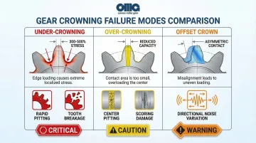
- Localized stress peaks can reach 300-500% of nominal calculated stress
- Rapid pitting and spalling initiate at tooth edges
- Tooth breakage occurs at face width extremes under shock loads
Edge contact also generates excessive noise:
- Abrupt load transitions create high-frequency excitation
- Transmission error increases dramatically compared to properly crowned gears
In aircraft high-lift actuation systems, edge loading from gear deflection represents a primary failure mode. Proper crowning concentrates bearing contact away from edges, preventing catastrophic failures in critical aerospace applications.
Over-Crowning Consequences
While under-crowning causes edge problems, excessive crowning creates the opposite issue—concentrating loads in too narrow a center band:
Reduced effective face width limits load distribution:
- Contact stress increases beyond material capacity
- Center pitting or scoring develops
- Load capacity is reduced despite adequate face width
Profile contact suffers as well:
- Excessive crown limits the usable tooth profile
- Transmission error increases rather than decreases
- Noise may increase despite the intent to reduce it
Improper Crown Location
Even with correct crown amount, asymmetrical placement causes problems when symmetrical crowning is required:
- Uneven load distribution across the face
- One edge may still experience loading despite crowning
- Gear may run quieter in one rotation direction than the other
| Crowning Issue | Primary Consequence | Performance Impact |
|---|---|---|
| Under-crowning/Absent | Edge loading and stress concentration | Premature failure, noise increase |
| Over-crowning | Center band overload | Reduced capacity, potential scoring |
| Offset crown | Asymmetric load distribution | Directional noise variation |
Common Misinterpretations of Gear Crowning in Practice
Treating crowning as a universal solution: Crowning cannot compensate for excessive misalignment (beyond ~0.004"), gross manufacturing errors, or inadequate gear quality. It's an optimization tool for real-world conditions, not a fix for poor design or sloppy assembly.
Systems with misalignment exceeding the crown's compensation range will still experience edge loading.
Assuming more crowning is always better: Excessive crown reduces load capacity and can increase noise rather than reduce it. Optimal crowning is application-specific and requires calculation or testing.
A gear with 0.004" crown in a rigid, well-aligned housing will perform worse than one with 0.001" crown matched to actual deflections.
Different gear types require adjusted crowning approaches: Helical gears have inherent axial load components and different contact patterns than spur gears. Crown amounts and profiles must be adapted.
Typically, helical gears require slightly less lead crown than equivalent spur gears due to the helix angle's effect on load distribution.
Ignoring the interaction between lead and profile crowning: Specifying lead crowning without considering profile modifications (tip relief) can create interference conditions during tooth engagement.
Key integration requirements:
- Design lead and profile crowning together, not independently
- Account for tip relief in the overall modification strategy
- Optimize contact throughout the entire mesh cycle
- Test combined effects under actual load conditions
Conclusion
Gear crowning transforms tooth contact from a potential failure point into an optimized load distribution mechanism. By deliberately creating a convex tooth surface, crowning prevents the edge loading that causes stress concentrations, premature wear, and excessive noise in real-world gear systems.
Understanding crowning types is essential for specifying gears that will survive their intended service life:
- Lead crowning (0.0005"-0.004" typical) compensates for misalignment
- Profile crowning (0.0002"-0.0008" typical) optimizes tooth engagement
- Optimal crown amount balances misalignment compensation, load capacity, noise reduction, and manufacturing capability
Engineering judgment in specifying crowning requires analyzing expected deflections, tolerances, and operating conditions. Published guidelines and AGMA standards provide starting points, but optimal crowning often requires application-specific analysis and prototype testing.
For precision applications requiring custom crowning specifications—particularly in aerospace, defense, and medical sectors—working with experienced gear manufacturers ensures the crowned geometry matches real-world operating conditions. Contact pattern validation and iterative refinement help achieve the noise reduction and performance optimization your application demands.
Frequently Asked Questions
What is profile crowning in gears?
Profile crowning removes material along the tooth height (involute direction) to create slight relief toward the tip and root, typically 0.0002"-0.0008". This prevents edge contact and eliminates interference as teeth engage and disengage.
What is profile correction in gears?
Profile correction (profile shift) changes tooth geometry by shifting the cutting tool during manufacturing, altering tooth thickness and proportions. Crowning is a secondary operation that removes material from already-cut teeth to optimize contact patterns.
When is gear crowning necessary versus optional?
Necessary for heavily loaded gears, applications with shaft deflection or misalignment, high-speed gears where noise is critical, and any system with edge loading. Optional for lightly loaded, slow-speed gears in rigid housings with precise alignment.
How is the optimal amount of crowning determined?
Engineers calculate crowning based on shaft deflection, tolerances, and housing stiffness, starting with AGMA guidelines (crown = 1/2 to 1/3 of expected misalignment). The values are refined through prototype testing and Prussian blue contact pattern analysis under load.
What's the difference between lead crowning and profile crowning?
Lead crowning creates a barrel shape along the face width (0.0005"-0.004") to compensate for misalignment. Profile crowning removes material along tooth height (0.0002"-0.0008") to prevent interference. Precision gears often use both.
Can crowning be added to existing gears that are experiencing edge loading?
Yes, if sufficient stock remains and the material is grindable. This salvages gears with heat treatment distortion or edge loading. The gear requires precision grinding equipment capable of AGMA 13 tolerances, like the capabilities at Carnes-Miller Gear.