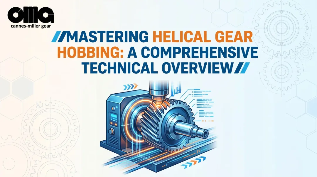
Introduction
Gear hobbing is a machining process that uses a specialized rotating cutting tool (hob) to progressively cut teeth into cylindrical gear blanks through synchronized rotational motion.
Manufacturing engineers, production managers, and OEMs in aerospace, defense, medical, and industrial sectors need to understand gear hobbing for production planning, quality requirements, and sourcing decisions.
Gear hobbing accounts for approximately 70% of the external gear manufacturing market globally. Yet many engineers struggle with selecting the right process for their batch size, understanding what AGMA quality ratings are realistically achievable, and knowing when hobbing's limitations make alternatives more practical.
The factors affecting quality, setup requirements, and when to use alternatives remain unclear at an operational level.
This article explains how gear hobbing works mechanically, what variables affect gear quality, how it compares to other methods, and when it's the optimal choice for your application.
TLDR
- Uses a helical cutting tool rotating in sync with a gear blank to progressively form teeth through continuous cutting
- Dominates gear manufacturing with speed, precision (AGMA A4-A6), and cost-effectiveness for batches over 500 units
- Depends on coordinated rotation at precise speed ratios as the hob feeds across the blank to desired depth
- Quality depends on hob precision (≤10 µm runout for Class AA), machine rigidity, and synchronization accuracy
What Is Gear Hobbing?
Gear hobbing is a machining process where a rotating helical cutting tool (hob) generates gear teeth through continuous cutting action as both the hob and gear blank rotate in synchronized motion.
The hob resembles a worm gear with relieved cutting edges. As it rotates in precise coordination with the workpiece, it gradually cuts material away to form the gear tooth profile.
The outcome is a precision gear with teeth formed to specific profiles (involute or cycloidal), dimensions (module or diametral pitch), and quality standards.
Modern CNC hobbing machines deliver impressive accuracy:
- Spindle synchronization of ≤0.001°
- AGMA A4-A6 (ISO 6-8) quality levels directly off the machine
- Achievable when using Class AA hobs
Understanding how hobbing compares to other gear cutting methods helps you select the right process for your application.
How hobbing differs from alternatives:
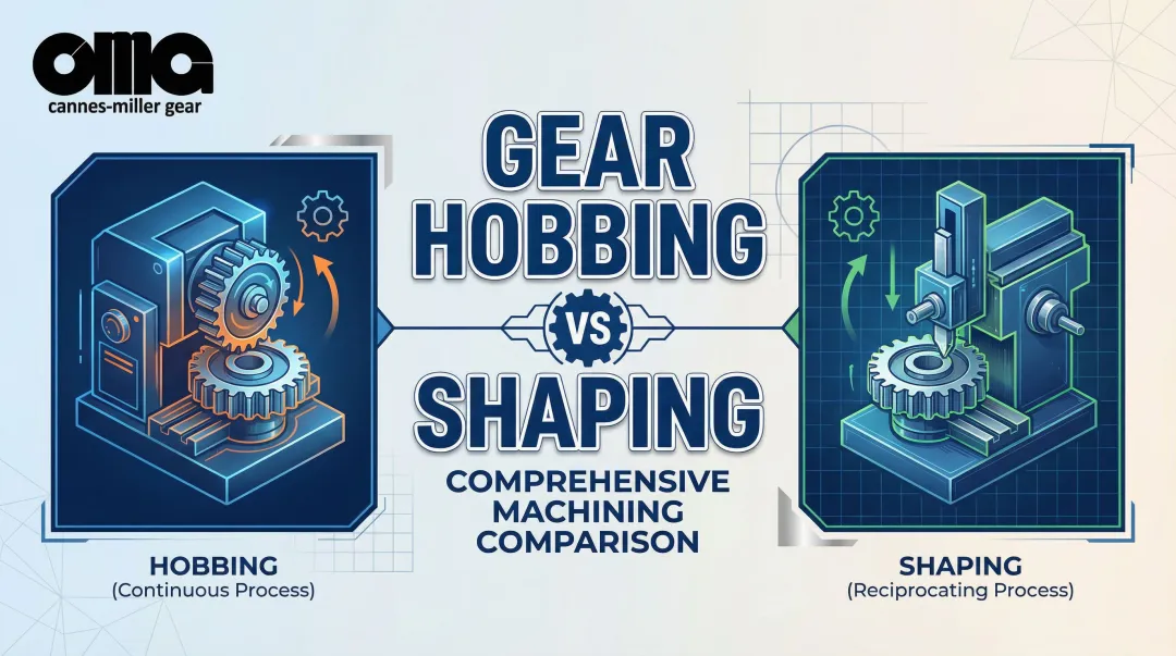
- Gear shaping: Uses a reciprocating cutter that moves up and down like a vertical shaper; can cut internal gears and gears with shoulders close to teeth where hobbing cannot reach
- Gear milling: Cuts one tooth gap at a time using an indexing process rather than continuously generating all teeth simultaneously; slower but more flexible for small batches
- Power skiving: Newer technology using a pinion-like cutter at a cross-axis angle; faster than shaping for internal gears and can machine closer to shoulders
Why Gear Hobbing Is Used in Manufacturing
Gear hobbing is adopted for its speed advantage—it's 4-10 times faster than gear shaping for external gears and more economical than broaching for medium to high volumes.
The economic breakpoint typically occurs at batch sizes exceeding 500 units, where hobbing's unit costs drop approximately 30% compared to milling.
Manufacturing demands hobbing addresses:
- Consistent involute tooth profiles for smooth meshing and minimal backlash
- Repeatable quality across production runs with minimal variation
- Ability to achieve tight tolerances (DIN quality grades 5-8, equivalent to AGMA A4-A8)
- Cost control through efficient material removal and shorter cycle times
- Flexibility to produce spur gears, helical gears, worms, and splines with the same machine
Consequences of poor hobbing quality:
Improperly controlled hobbing parameters produce gears with tooth spacing errors, profile deviations, and poor surface finish.
These defects lead to noise, vibration, premature wear, and potential system failures in critical applications like aerospace gearboxes or medical devices. In high-speed applications, even minor profile errors cause heat buildup and accelerated fatigue.
Hobbing is industry best practice for external spur and helical gears, preferred operationally for its balance of speed and precision.
The gear quality standards it achieves (AGMA 2015-1, DIN 3962, ISO 1328) are often specified in engineering drawings and procurement contracts, even when not driven by specific regulatory requirements.
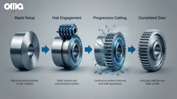
How the Gear Hobbing Process Works
The hob is a worm-shaped cutter with helical teeth and relieved cutting edges. Both the hob and gear blank are mounted on separate spindles set at a specific angle.
They rotate together at a fixed speed ratio determined by the number of teeth being cut and the number of threads (starts) on the hob.
Core transformation:
As the hob rotates and feeds across the blank face, its cutting teeth progressively remove material. Each tooth of the hob cuts a small chip, and the synchronized rotation ensures each successive cut forms the correct involute tooth profile. The blank transforms from a smooth cylinder to a toothed gear as material is removed.
Speed ratio formula:
Speed Ratio = Number of Gear Teeth ÷ (Hob Threads × 1)
For example, cutting a 40-tooth gear with a single-start hob requires the hob to rotate 40 times for every single revolution of the gear blank.
Multi-thread hobs (2 or 3 starts) reduce this ratio, increasing production speed but potentially introducing polygonal errors if synchronization is not precise.
This speed synchronization requires precise control, which bridges the mathematical formula to practical machine setup:
Process control elements:
- Electronically controlled in CNC machines or mechanically geared in conventional machines to maintain exact speed ratio
- Hob angle calculated based on lead angle plus gear helix angle (typically 15°-30° for standard applications)
- Radial feed controls depth, cutting into the blank until full tooth depth is achieved
- Axial feed determines how quickly the hob travels across the blank face
What goes into the process:
- Cylindrical gear blank pre-machined to specific outer diameter, bore, and face perpendicularity
- Precision hob matched to desired gear profile and module
- Cutting parameters (speeds, feeds, depth of cut) optimized for material and quality requirements
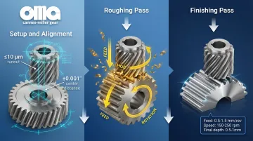
Step 1: Setup and Alignment
Mount the gear blank on the workpiece spindle using a mandrel or chuck. Mount the hob on the hob spindle at the calculated angle. Set the machine's gear train or CNC controller to maintain the correct speed ratio (e.g., 40:1 for a 40-tooth gear with single-thread hob).
Setup accuracy is critical. Incorrect hob angle, improper center distance, or inaccurate indexing directly translate to tooth form errors that cannot be corrected in subsequent passes.
Critical setup tolerances:
- Hob runout: ≤10 µm or 0.0004" Total Indicator Runout (TIR) for Class AA hobs
- Center distance accuracy within ±0.001"
- Angular positioning precise to ±2 arc-minutes
Step 2: Initial Engagement and Roughing
Feed the hob radially into the blank to a shallow depth, typically 50-70% of final tooth depth. It then feeds axially across the blank face. This roughing pass removes most material quickly and establishes the basic tooth form.
Typical roughing parameters:
- Alloy steel (soft): 80-120 m/min surface speed with coated HSS, 1.5-3.0 mm/rev feed
- Aluminum: 200-400+ m/min surface speed with carbide, 2.0-5.0 mm/rev feed
Roughing focuses on material removal rate over surface finish. Feed rates are higher, and cutting speeds are optimized for tool life rather than precision.
Step 3: Finishing Pass
After roughing, feed the hob to final depth and make a finishing pass (or multiple passes for high-quality gears) at optimized cutting parameters. This achieves final dimensions, surface finish (typically Ra 1.6-3.2 µm), and tooth profile accuracy required for the specified AGMA or DIN quality grade.
Finishing adjustments:
- Reduced feed rates (0.5-1.0 mm/rev for precision work)
- Optimized cutting speeds to minimize built-up edge
- Multiple light passes for AGMA A4 or better quality
- Sharp hobs with minimal wear to ensure accurate profile generation
For hardened materials exceeding HRC 45, standard hobbing becomes impractical due to rapid tool wear. In these cases, gears are hobbed in the soft state, heat-treated, then finished by grinding or hard skiving.
Where Gear Hobbing Is Applied
Gear hobbing serves multiple manufacturing contexts across diverse industries:
Systems and equipment:
- Automotive transmissions (planetary gears, differential ring gears, e-drive reduction gears)
- Industrial gearboxes (wind turbine drives, heavy-duty reducers, machine tool drives)
- Aerospace power transmission systems (helicopter accessory gearboxes, turbine reduction gears, APU drives)
- Agricultural machinery drives (tractor transmissions, harvester gearboxes)
- Mining equipment reducers (crusher drives, conveyor gearboxes)
- Precision instrument gears (medical device gears, robotics drives)
Manufacturing workflow integration:
Hobbing occurs during the "soft" machining stage before heat treatment. Manufacturers hob gears at 180-220 BHN hardness, then heat-treat them to HRC 58-62.
Many industrial applications use "hobbed and hardened" gears without grinding, as AGMA A7-A9 quality is adequate for most non-critical applications. Higher-precision applications require grinding or honing for final accuracy.
Common production scenarios:
- New gear production for OEM equipment manufacturing
- Replacement gears for aftermarket service and maintenance
- Prototype development and design validation
- Reverse engineering of obsolete gears where original tooling is unavailable
Hobbing functions as a recurring production process for ongoing manufacturing rather than a one-time maintenance activity.
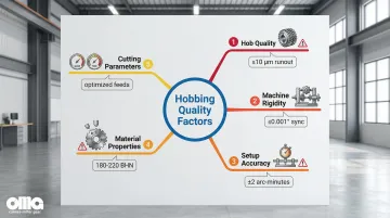
Key Factors That Affect Gear Hobbing Quality
Hob Quality and Condition
The hob must be precisely ground to the correct involute profile, sharp (dull hobs cause poor surface finish and dimensional errors), and properly coated. Carbide hobs enable cutting speeds 2-3x higher than HSS and last approximately four times longer between sharpenings.
Worn hobs produce gears with tooth spacing errors, profile deviations, and poor surface finish. To prevent these issues, hobs must meet strict specifications:
- Runout: ≤10 µm (0.0004" TIR) for Class AA hobs; up to 25 µm for Class B
- Helix angle accuracy: ±5 arc-minutes for precision work
- Relief angles: 5°-10° to ensure clearance without compromising edge strength
Regular inspection and resharpening are essential to maintain quality.
Machine Rigidity and Accuracy
Hobbing machines require precise spindle synchronization, minimal backlash in feed mechanisms, and rigid support to prevent deflection under cutting forces. Worn machines compromise accuracy and produce gears with indexing errors and form deviations.
Critical machine specifications:
- Spindle synchronization: ≤0.001° accuracy (modern CNC direct-drive systems)
- Positioning repeatability: ≤0.5 µm on high-end machines
- Thermal stability: Temperature-controlled environments for AGMA A4 or better work
Machine condition directly impacts achievable quality. A well-maintained gear shaper can outperform a worn hobbing machine, despite hobbing's theoretical advantages.
Setup Accuracy
Even the best machine requires proper setup to deliver precision results. Correct hob angle setting, proper center distance between hob and blank, accurate indexing, and secure workpiece clamping are critical. Setup errors directly translate to tooth form errors that cannot be corrected in subsequent passes.
Setup checklist:
- Verify hob angle calculation (lead angle + helix angle)
- Check center distance with precision measuring tools
- Confirm workpiece clamping rigidity (no deflection under cutting forces)
- Validate speed ratio programming or mechanical gearing
Even minor setup errors compound across all teeth, resulting in gears that fail inspection or exhibit poor meshing characteristics.
Material Properties and Blank Preparation
Gear blanks must be properly stress-relieved, have consistent hardness (typically 180-220 BHN for hobbing), and be accurately pre-machined. Bore, OD, and face squareness must meet specifications to ensure proper mounting and indexing.
Material variations cause inconsistent cutting forces and dimensional variations. Castings with porosity or inclusions can cause chipping and premature tool wear.
Blanks with residual stress may distort during cutting, leading to dimensional errors.
Cutting Parameters
Feed rate affects surface finish and chip formation. Too fast causes chatter and poor finish; too slow is inefficient and can cause work hardening. Cutting speed must match material and hob coating. Depth of cut affects tool life and accuracy—multiple light passes yield better quality than a single heavy pass.
Parameter optimization guidelines:
- Start with manufacturer recommendations for material/tool combination
- Monitor surface finish and adjust feed rate accordingly
- Track tool wear and adjust speeds to maximize tool life
- Use multiple passes for AGMA A6 or better quality requirements
Balancing productivity with quality requires careful parameter selection. Aggressive settings may reduce cycle time but often increase scrap rates and tool costs—making conservative approaches more cost-effective overall.
Comparison: Gear Hobbing vs. Other Gear Manufacturing Methods
Hobbing vs. Gear Shaping
Hobbing is faster and more economical for external gears but cannot cut internal gears or gears with shoulders close to teeth. Shaping's reciprocating cutter reaches where hobs can't.
Key differences:
- Speed: Shaping runs 3-5x slower than hobbing for external gears
- Quality: Both achieve comparable results (AGMA A6-A8) when properly controlled
- Applications: Shaping remains the standard for internal gears and tight geometric constraints
Hobbing vs. Gear Broaching
Broaching is faster for high-volume internal gear production (one stroke vs. continuous cutting) but requires expensive dedicated broaches for each gear design. A single broach can cost $5,000-$50,000 depending on size and complexity.
Economic breakpoint: Broaching becomes cost-effective only above 10,000 units.
Hobbing offers greater flexibility for design changes and lower volumes. Hobs cost less than broaches and can be resharpened multiple times, reducing tooling costs for medium-volume production.
Hobbing vs. Gear Milling
Gear milling cuts one tooth space at a time using an indexing process. It's slower than hobbing but offers extreme flexibility—the same cutter can produce multiple gear sizes by adjusting depth and indexing.
Major advantage: Milling can be done in standard machining centers without dedicated gear machines.
Hobbing requires dedicated machines but is more productive for volumes above 50-100 pieces. For prototypes and small batches (under 50 units), milling is often more economical due to lower setup overhead.
Hobbing vs. Power Skiving
Power skiving is newer technology that's 3-8x faster than shaping for internal gears and can machine closer to shoulders. It uses a pinion-like cutter at a cross-axis angle (typically 10°-25°), combining the rolling motion of hobbing with axial cutting.
Hobbing remains more established with broader machine tool availability and is preferred for external spur and helical gears. Skiving excels for internal gears, gears with interference contours, and applications requiring turning and gear cutting in a single setup.
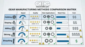
Process Comparison Table
| Method | Speed | Quality (AGMA) | Gear Types | Economic Batch | Machine Cost |
|---|---|---|---|---|---|
| Hobbing | 1.0x (baseline) | A4-A8 | External spur/helical | 500+ units | High ($1M+) |
| Shaping | 0.2-0.3x | A4-A8 | Internal, shoulders | <100 units | Medium ($500K) |
| Milling | 0.3-0.7x | A6-A10 | All types | <50 units | Low ($200K) |
| Skiving | 0.3-1.0x | A4-A6 | Internal, hardened | 100-10,000 units | Very High ($1.5M+) |
| Broaching | 2.0x (internal) | A6-A8 | Internal, splines | 10,000+ units | Medium ($500K) |
Speed is relative to hobbing for external gears; skiving speed advantage is most pronounced on internal gears vs. shaping.
Common Issues and Misconceptions
"Hobbing Always Produces Better Quality Than Other Methods"
Quality depends on machine condition, setup accuracy, and operator skill—not the process itself. A well-maintained shaper with a skilled operator can outperform a worn hobbing machine with poor setup.
Process selection should be based on gear geometry, batch size, and available equipment capabilities, not assumptions about superior quality.
"Hobbing Is Only for High Volume"
While most economical at higher volumes (500+ units), hobbing is often used for prototypes and small batches (10-50 pieces) when the gear design suits hobbing and quality requirements are high.
The key consideration is whether the setup time and tooling costs are justified by the precision and cycle time advantages, not just batch size.
"Multi-Thread Hobs Always Cut Faster"
Multi-thread hobs (double, triple) do cut faster by reducing required rotations—a double-start hob needs only 20 rotations to cut a 40-tooth gear instead of 40.
However, single-thread hobs generally produce more accurate gears because synchronization errors are minimized. Use multi-thread hobs for roughing or when cycle time is critical and quality requirements are moderate (AGMA A8 or lower).
"Any Gear Defects Can Be Fixed by Grinding"
Grinding can correct minor tooth profile errors and improve surface finish (achieving Ra 0.2-0.4 µm), but it cannot fix major tooth spacing errors. If hobbing produces gears with significant pitch deviations or runout errors, grinding will not salvage them.
Consider these factors when deciding whether grinding is necessary:
- AGMA A7-A9 hobbed gears are adequate for most industrial applications where noise and vibration aren't critical
- Grinding adds significant cost and cycle time
- Many applications don't require grinding if hobbing quality is sufficient
- Specify grinding only when performance requirements justify the added expense
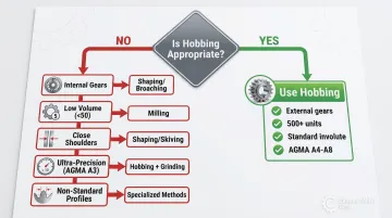
When Gear Hobbing May Not Be Appropriate
While gear hobbing offers efficiency for many applications, certain scenarios call for alternative manufacturing methods. Understanding these limitations helps manufacturers select the most practical and cost-effective process for their specific requirements.
Low Volume Production
For very low volumes (1-10 pieces), gear milling in a machining center is more economical. Setup time for hobbing (mounting the hob, setting angles, programming speed ratios) can exceed the actual cutting time for small batches. Milling uses standard CNC equipment and requires less specialized setup.
Internal Gears
The hob cannot reach inside a gear blank due to geometric constraints, making hobbing unsuitable for internal gears. Gear shaping with a reciprocating cutter or broaching handles these applications effectively. Power skiving has emerged as a faster alternative to shaping for internal gear cutting.
Gears with Shoulders or Flanges Close to Teeth
Insufficient hob clearance prevents hobbing when shoulders or flanges sit within 5-10 mm of the gear teeth. The hob requires runout space at the end of the cut. Gear shaping cuts vertically and works close to shoulders, while power skiving cuts up to shoulder faces—both gear shaping offer practical solutions.
Very Small Module Gears
For gears below 0.5 module (50 diametral pitch), hob concentricity and tool fragility become limiting factors. Manufacturers struggle to produce small hobs with adequate precision, and their small diameter makes them prone to deflection under cutting forces. Consider gear milling or wire EDM for very fine pitch gears.
Ultra-High Precision Requirements
Gears requiring AGMA A3 (ISO 4) or better quality typically need grinding after hobbing. While modern CNC hobbers can achieve A4 quality, tighter tolerances require post-process finishing to correct minor errors and improve surface finish. When specifications demand ultra-high precision, factor grinding into project timelines—facilities like Carnes-Miller Gear offer grinding services up to 400mm diameter with AGMA 13 ratings on ground spur gears.
Non-Standard Tooth Profiles
Worm wheels with throated profiles, bevel gears, and gears with interrupted tooth forms require different cutting methods. Hobbing works best for standard involute profiles on external spur and helical gears. Unusual tooth geometries may require specialized hobbing setups that negate the process advantages, making alternatives more practical.
Conclusion
Gear hobbing is a continuous cutting process using synchronized rotation of a helical hob and gear blank to progressively form gear teeth. It offers an optimal balance of speed, precision, and cost-effectiveness for external spur and helical gears in medium to high production volumes (typically 500+ units).
Understanding the factors affecting hobbing quality—hob condition (≤10 µm runout for Class AA), machine accuracy (≤0.001° synchronization), setup precision, and material properties—enables manufacturers to make informed decisions about production methods, quality expectations, and when to outsource to specialists.
The transition to AGMA A-grade standards (where lower numbers indicate higher precision) requires careful attention to avoid quality misinterpretations on legacy drawings.
Correct application matters more than blind adoption. Evaluate these factors to determine if hobbing is the right choice:
- Batch size and production volume requirements
- Quality specifications (AGMA A4-A8 achievable through hobbing alone)
- Gear geometry (external vs. internal, shoulder clearances)
- Available equipment and in-house capabilities
Alternatives like shaping (for internal gears), milling (for small batches), or power skiving (for interference contours) may better suit specific applications and production constraints.
When projects require AGMA A6 or better quality, specialized gear profiles, or reverse engineering of obsolete components, partnering with an experienced gear manufacturer ensures optimal results.
Carnes-Miller Gear brings over 50 years of precision gear manufacturing expertise to aerospace, defense, medical, and industrial applications—reach out to discuss your specific gear manufacturing needs.
Frequently Asked Questions
What is a gear hobber?
A gear hobber is a specialized machine tool that cuts gears using a rotating helical cutting tool called a hob. It features synchronized spindles for the hob and workpiece, with modern CNC versions offering ≤0.001° synchronization accuracy for precision manufacturing.
What is the difference between gear hobbing and gear broaching?
Hobbing is a continuous rotary process for external gears with resharpable tooling. Broaching is a linear single-stroke process primarily for internal gears and splines in high-volume production (10,000+ units), requiring dedicated tooling investment of $5,000-$50,000 per broach.
What is spline hobbing?
Spline hobbing applies the hobbing process to cut splines (multiple parallel keys on a shaft) using a spline hob. It produces involute splines, straight-sided splines, or serrations commonly used in automotive driveshafts, machine tool spindles, and power transmission components, offering the same speed and consistency advantages as gear hobbing.
What are the types of splines?
The main types are involute splines (most common, governed by ANSI B92.1, self-centering), straight-sided splines (parallel flanks per ANSI B92.2), and serrations (fine-pitch teeth for high-torque connections). Each suits different load transmission requirements and can be produced through hobbing, broaching, or milling.
Can a spline be repaired?
Worn or damaged splines can sometimes be repaired if profile wear is less than 0.2 mm (0.008") by building up material through welding or thermal spray coating, then re-machining to original dimensions. However, for critical applications, replacement is often recommended to ensure proper fit, load distribution, and reliability, as repairs may not restore full structural integrity.
What quality standards apply to hobbed gears?
Hobbed gears are classified by AGMA 2015-1 standards (A4-A8 achievable, with lower numbers indicating tighter tolerances) or DIN 3962 standards (quality grades 5-8 common). These specify tolerances for tooth profile, spacing, runout, and surface finish, with the current system aligned to ISO 1328.