This article explains what double helical gears are, how they function, key design parameters, and when they are the optimal choice for specific applications.
Key Takeaways
- Opposing helix angles cancel axial thrust, eliminating thrust bearing needs
- Contact ratios exceed 2.0 for smoother, higher-torque transmission than spur gears
- Best suited for turbomachinery, marine propulsion, and heavy equipment minimizing vibration and noise
- Manufacturing complexity justifies cost in applications requiring balanced axial forces and maximum load capacity
- Precision manufacturing ensures proper load distribution and operational reliability
What Are Double Helical Gears?
Double helical gears feature two sets of helical teeth with opposite helix angles—one left-hand and one right-hand—arranged in a V-pattern on the same gear body. This design creates a fundamental mechanical advantage: the axial thrust forces generated by each helical section cancel each other out.
Key characteristics include:
- Opposing helix angles that neutralize axial thrust
- Balanced load distribution across gear faces
- No requirement for thrust bearings
- Compact gearbox designs with reduced weight
The elimination of axial thrust forces removes the need for heavy thrust bearings and allows for more compact gearbox designs. Research indicates this design can reduce axial bearing loads by approximately 80% compared to single-helical designs.
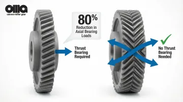
This simplifies bearing arrangements and reduces maintenance requirements.
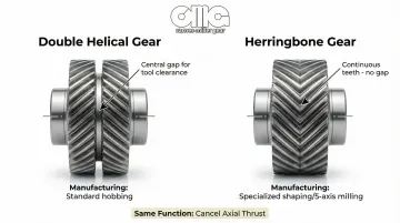
Double Helical vs. Herringbone Gears
Understanding the manufacturing distinction helps when specifying gears for custom applications. While the terms are sometimes used interchangeably, there are practical differences:
Double helical gears:
- Include a central gap between the two tooth sections
- Provide clearance for cutting tools during hobbing or grinding
- Simplify production using standard hobbing machines
Herringbone gears:
- Feature continuous teeth with no gap
- Form an uninterrupted V-pattern
- Maximize face width but require specialized shaping or 5-axis milling
Both serve the same functional purpose—canceling axial thrust—but differ in how they're manufactured. The choice between them often depends on available machining capabilities and specific application requirements.
How Double Helical Gears Work
As the gear rotates, both the left-hand and right-hand helical sections engage simultaneously with the mating gear. Each section generates an axial thrust force, but these forces act in opposite directions.
When properly designed and manufactured, these opposing forces cancel each other out completely. This self-balancing design eliminates the need for thrust bearings in many applications.
Smooth Torque Transmission
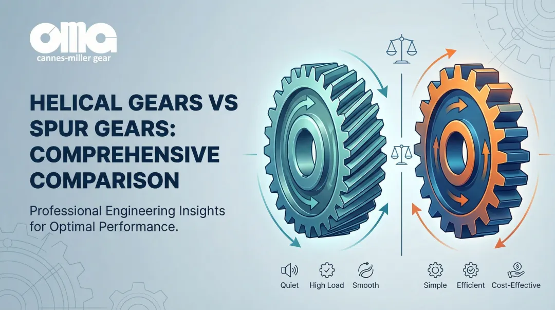
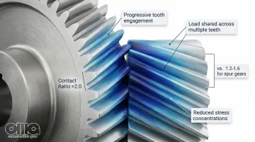
Continuous tooth engagement across both sections provides smoother torque transmission and higher contact ratios compared to spur gears. Double-helical gears typically achieve contact ratios exceeding 2.0, meaning at least two pairs of teeth are in contact at all times, compared to 1.2-1.6 for spur gears.
This high contact ratio delivers three key performance advantages:
- Teeth engage progressively rather than impacting across the full face width simultaneously
- Multiple teeth sharing the load minimizes transmission error fluctuations
- Smooth engagement eliminates the characteristic whine of spur gears
Load Distribution
Double helical gears distribute load across multiple teeth simultaneously, reducing stress concentrations and improving load-carrying capacity. The helix angle, face width, and tooth profile work together to determine stiffness characteristics and operational smoothness.
Testing has confirmed these gears can operate without thrust bearings entirely, simplifying lubrication and support systems in high-speed applications.
Design Considerations and Key Parameters
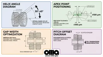
Helix Angle Selection
Helix angle is a critical parameter—typically ranging from 30° to 45° for double helical gears—that affects thrust force cancellation, contact ratio, and smoothness of operation. Higher helix angles increase the face contact ratio, leading to smoother operation, but also increase potential sliding friction.
Single helical gears typically use 15°-25° angles to limit thrust. Double helical designs allow steeper angles to maximize smoothness without generating massive thrust loads.
Apex Point Positioning
The apex point is the theoretical intersection of the two helix sections. Its positioning critically affects load distribution between gear halves.
Research shows the apex point must be controlled within ±100 µm. Manufacturing deviations beyond this tolerance cause:
- Unbalanced loading between the two helical sections
- One helix carrying significantly more load than the other
- Increased vibration and uneven wear
- "Apex runout" where the apex point wobbles axially during rotation
Gap Width Optimization
For double helical gears with a central gap, the width depends on manufacturing tool clearance requirements. Smaller gaps increase power density but complicate manufacturing.
Key considerations:
- Smaller gaps increase effective face width and power density
- Advanced 5-axis milling enables gaps as small as 10mm, improving power density by approximately 7%
- Gap width must provide sufficient clearance to prevent tool damage during hobbing or grinding
Pitch Offset Optimization
The relative rotational position between the two gear halves affects transmission error and excitation frequencies. Staggering the teeth by 0.5 pitch offset reduces peak-to-peak static transmission error by approximately 30%.
This effectively doubles the meshing frequency while halving excitation force amplitude.
Profile Modifications
Profile modifications such as crowning and tip relief must be applied to both gear sections to accommodate deflections, misalignments, and manufacturing tolerances while maintaining balanced load sharing. Studies show that adding lead crowning and tip relief can reduce transmission error fluctuations by up to 25%, improving operational smoothness and extending gear life.
Advantages and Limitations
Key Advantages
Double helical gears deliver distinct performance benefits that make them valuable despite their complexity:
- Thrust elimination: The opposing helices completely cancel axial thrust forces, reducing bearing loads and costs while allowing simpler gearbox housing designs and improved reliability in critical applications.
- High load capacity: Double helical gears are noted for having the highest load capacity among parallel shaft gears. Continuous engagement and wide face widths without thrust penalties make them ideal for high-torque applications.
- Smooth and quiet operation: High contact ratios create gradual tooth engagement that significantly reduces noise and vibration compared to spur gears.
- High-speed capability: The balanced design handles high rotational speeds without the bearing complications of single helical gears.
- Improved efficiency: Eliminating friction losses from large thrust bearings increases system efficiency, particularly in high-power marine and turbine applications.
Primary Limitations
These advantages come with trade-offs that affect both production and application decisions:
- Manufacturing complexity: Producing double helical gears requires complex machining processes, often involving two setups or specialized equipment. Finishing teeth near the gap or apex presents particular challenges.
- Higher cost: The manufacturing complexity translates directly to higher production costs compared to single helical or spur gears.
- Inspection challenges: Quality control is more demanding. Verifying alignment of the two helices, apex coincidence, and checking for runout requires advanced measurement equipment. Apex position errors represent a unique failure mode that doesn't exist in single-helical gears.
- Limited off-the-shelf availability: Most double helical gears are custom manufactured to specification—a requirement that specialized job shops like Carnes-Miller Gear address through comprehensive in-house manufacturing capabilities.
- Precise alignment requirements: Assembly requires careful alignment to maintain balanced load distribution between the two helical sections.
When Double Helical Gears May Not Be Cost-Effective
Given these limitations, cost considerations matter. These gears may not justify their expense in low-power applications, short production runs, or situations where axial thrust can be managed economically with thrust bearings.
For applications under 50 HP with moderate speeds, single helical gears with thrust bearings often provide better value.

Applications and Use Cases
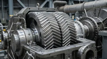
Turbomachinery and Power Generation
Double helical gears are standard in steam and gas turbine reduction gearboxes that demand high speeds, heavy loads, and axial thrust elimination. OEMs like Flender and Siemens Energy use these gears in turbo gear units capable of speeds up to 40,000 RPM and power ratings of 100 MW.
The thrust cancellation protects the high-speed hydrodynamic bearings used in these turbines.
Generator drives connecting high-speed turbines to generators rely on double helical gears to ensure smooth, reliable power transfer with minimal vibration that could damage sensitive electrical components.
Marine Propulsion Systems
Large vessels use double helical gears in main reduction gearboxes to transmit engine power to propellers with minimal vibration and bearing loads. RENK and Flender supply double-helical marine gearboxes rated up to 50,000 kW per engine.
Key advantages in marine applications:
- Minimizes noise and vibration for passenger ships and naval vessels
- Controls acoustic signatures for stealth operations
- Cancels internal gear thrust while maintaining balanced bearing loads
- Includes separate main thrust bearing for propeller thrust
Heavy Industrial Equipment
Double helical gears handle demanding applications in steel, mining, and manufacturing industries requiring exceptional durability and torque capacity.
Common industrial applications include:
- Rolling mills: David Brown Santasalo supplies double-helical gears for steel mills that withstand immense, reversing torque loads and allow drop-in replacements to upgrade existing mill stands
- Extruders and crushers: Handle high torque and thrust loads in rubber and plastic extrusion drives, with integral thrust bearings for the screw while gears remain thrust-neutral
- Conveyors: Provide reliable power transmission in heavy-duty material handling systems
Aerospace and Defense
Applications include gearboxes in auxiliary power units (APUs), helicopter transmissions, and other systems with strict weight, noise, and reliability requirements. NASA and Bell Helicopter tested double-helical gears in helicopter transmissions to eliminate heavy thrust bearings and improve efficiency.
Test results confirmed these gears could operate without thrust bearings and simplify lubrication systems—crucial advantages for aerospace applications.
Oil and Gas Drilling Equipment
Double helical gears handle extreme loads and harsh operating conditions in drilling systems and compressors on offshore platforms. High-speed compressor drives use these gears to ensure reliability and minimize maintenance in remote environments where downtime is extremely costly.
Manufacturing and Quality Considerations
Manufacturers produce double helical gears using gear hobbing, gear shaping, or 5-axis CNC milling. High-precision applications require grinding to achieve AGMA quality grades of 10-13.
Manufacturing Methods
Hobbing — The most common method for double helical gears with a central gap. The gap allows the hob cutter to run out without hitting the opposing helix.
Shaping — Required for herringbone gears with no gap or very narrow gaps. Shapers use a reciprocating cutter that can stop precisely at the apex.
5-axis milling — Increasingly used for producing prototypes or large gears with complex geometries. Machines both helices and the apex in a single setup. This improves alignment accuracy significantly.
Grinding — Essential for achieving AGMA Q10-Q13 precision grades required in high-speed applications. Modern profile grinding machines can finish double-helical gears provided there is sufficient gap for the grinding wheel.
Inspection Requirements
Achieving the tight tolerances these gears demand requires specialized measurement equipment to verify:
- Helix angle accuracy on both sections
- Apex point position and runout
- Tooth profile modifications
- Load distribution across both gear halves
AGMA 915-2 recommends radial composite (double flank) testing to verify tooth geometry and runout.
The apex alignment check is critical. Deviations must be controlled to prevent dynamic shuttling forces during operation.
Quality Standards and Manufacturing Expertise
Double helical gears for aerospace, defense, and industrial applications require manufacturers with precision grinding capabilities and quality control expertise. Carnes-Miller Gear provides gear grinding up to 400mm diameter, achieving AGMA 13 ratings on ground gears, the precision level these applications demand.
Custom projects requiring exact specifications, reverse engineering capabilities, or specialized inspection procedures benefit from manufacturers with comprehensive in-house capabilities. This ensures proper apex alignment, balanced load distribution, and the reliability critical to turbomachinery and heavy industrial applications.
Frequently Asked Questions
What are the benefits of double helical gears?
These gears cancel axial thrust forces, handle higher loads, and run more smoothly and quietly than spur gears. They reduce the need for heavy thrust bearings, making them ideal for high-power applications where reliability and compact design are priorities.
What is the basic difference between a double helical and herringbone gear?
Double helical gears have a central gap between helical sections for tool clearance, while herringbone gears have continuous teeth with no gap. Both cancel axial thrust, but herringbone gears need specialized manufacturing like shaping or 5-axis milling.
What is the 17 teeth rule for gears?
The 17-tooth minimum (at 20° pressure angle) prevents undercutting in standard gears. For double helical gears, this applies to each helical section. Designs with fewer teeth need modifications like profile shifting to maintain tooth strength.
When should you choose double helical gears over single helical gears?
Choose them when you need to cancel axial thrust and reduce bearing loads, in high-power applications requiring maximum load capacity, or where smooth operation and gearbox compactness justify higher manufacturing costs.
What industries commonly use double helical gears?
Primary users include power generation, marine propulsion, heavy industrial equipment (steel mills, mining, extruders), aerospace and defense, and oil and gas drilling. These sectors demand thrust elimination, high load capacity, and proven reliability.
How do double helical gears reduce noise compared to spur gears?
The helical tooth design creates gradual engagement with multiple teeth in mesh simultaneously, reducing impact forces, vibration, and noise. Spur gears have sudden, full-face engagement that produces higher noise levels.