Introduction
Gear tooth profile measurement is critical for ensuring proper gear mesh, smooth operation, and longevity in high-performance applications across aerospace, medical, and industrial sectors. Even minor profile errors can increase vibration and gear rattle significantly.
Research shows that profile inaccuracies are a primary driver of mechanical failure. In aerospace applications, these failures can result in serious financial and safety consequences.
Inaccurate profiles lead to noise, premature wear, vibration, and potential system failure. Quality control engineers must prevent these problems through precise measurement.
This guide covers proven measurement methods, how to interpret results accurately, and the most common pitfalls that compromise gear quality in manufacturing environments.
Key Takeaways
- Verifies involute accuracy, tooth thickness, and geometry for reliable gear mesh
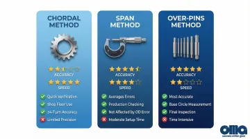
- Three methods: chordal (quick), span (production), over-pins (precision)
- Critical factors: proper tools, 68°F ±2°F environment, correct measurement points
- Compare results to AGMA grades (A2-A11) or design specs for acceptance
- Common errors: wrong pin size, incorrect points, unstable setup, temperature drift
What You Need to Measure Gear Tooth Profiles
Successful measurement depends on selecting appropriate tools based on gear type, required accuracy level, and whether you're checking tooth thickness, involute shape, or both.
Tools and Measurement Devices
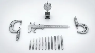
Essential measurement tools include:
- Gear tooth vernier caliper: Chordal measurements with ±4 µm to ±7 µm accuracy
- Span micrometers: Span measurements over multiple teeth
- Precision pins or balls: 0.8mm to 8.731mm diameters, covering modules 0.5 to 5.25
- Outside micrometers: Over-pins method, preferably with ratchet stop for consistent pressure
- Dial indicators: Setup verification and runout checking
- CMM or gear analyzer (optional): Complex profiles and fine pitch gears below 0.5 module
You'll also need appropriate reference standards for verification.
Reference standards needed:
- AGMA 2015 series standards: Current accuracy grades A2-A11 (replacing legacy AGMA 2000-A88 Q3-Q15 system)
- Gear design drawings: With specified tolerances and pressure angles
- Calibrated master gears: For comparison methods in production environments
Measurement Environment and Setup Requirements
Environmental conditions directly affect measurement accuracy. A 100mm steel gear measured at 21°C (just 1°C off standard) expands by approximately 1.15 µm—enough to consume significant tolerance in high-precision grades.
Required conditions:
- Temperature: 68°F ±2°F (20°C ±1°C) per ISO standard reference
- Stability time: Minimum 2 hours for large gears to reach equilibrium
- Workspace: Clean, debris-free environment with adequate lighting
- Mounting: Secure gear between centers, keeping runout below 0.001"
- Accessibility: Full access to measure multiple teeth at spaced positions
Methods to Measure Gear Tooth Profile
Choosing the right measurement method depends on your precision requirements, production volume, and available equipment. Three proven approaches cover everything from quick shop floor checks to precision final inspection.
Method 1: Chordal Tooth Thickness Measurement
Description: This method measures tooth thickness as a straight-line chord at a specific depth from the tooth tip. Using a specialized gear tooth vernier caliper, it's the fastest approach for quick verification.
Tools needed:
- Gear tooth vernier caliper with depth and width scales
- Calculated chordal addendum and chordal thickness values
Calculation formulas:
- Chordal thickness: $g_c = d \cdot \sin(90° / z)$
- Chordal addendum: $h_c = m + \frac{g_c^2}{4d}$
Where $d$ = pitch circle diameter, $z$ = number of teeth, $m$ = module
Step-by-step process:
- Calculate theoretical chordal thickness and addendum using gear parameters
- Set caliper depth scale to chordal addendum value
- Place caliper perpendicular to tooth centerline
- Measure width at specified depth with consistent pressure
- Repeat on minimum 4 teeth equally spaced around the gear per ISO 1328-1 recommendations
Pros: Quick shop floor verification, minimal equipment, good for incoming inspection
Cons: Less accurate than other methods (measures chord not actual arc), sensitive to caliper positioning errors, difficult on small gears, relies on outside diameter as reference which itself has tolerances
Method 2: Span Measurement Over Teeth
Description: This approach measures the distance over a specific number of teeth using a span micrometer. It verifies average tooth thickness and spacing across multiple teeth at once.
Tools needed:
- Span micrometer or outside micrometer with flat anvils
- Calculation to determine optimal number of teeth to span (typically results in measurement angle close to pressure angle)
Step-by-step process:
- Calculate theoretical span dimension and number of teeth to span using gear specifications
- Place micrometer anvils to contact tooth flanks symmetrically over the calculated number of teeth
- Apply consistent measuring pressure (use ratchet stop if available)
- Record measurement
- Rotate gear and repeat at 3-4 positions around the gear
- Compare actual measurements to calculated theoretical span
Pros: Averages out individual tooth errors, not affected by outside diameter error, good for production checking, relatively quick
Cons: Requires calculation of span teeth number, cannot identify individual tooth problems, limited to external spur and helical gears, minimum face width required for helical gears
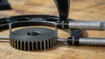
Method 3: Over-Pins (Ball) Measurement
Description: This is the most accurate method for tooth thickness measurement. It measures the dimension over two precisely sized pins or balls placed in opposite tooth spaces, directly relating to tooth thickness on the base circle.
Tools needed:
- Precision measurement pins or balls (size calculated to contact tooth flank at or near pitch circle)
- Outside micrometer or specialized over-pins micrometer
- Calculation of theoretical measurement over pins
Ideal pin diameter calculation: For spur gears: $d_p \approx \frac{\pi \cdot m}{2} \cdot \cos(\alpha)$
Where $m$ = module, $\alpha$ = pressure angle
Step-by-step process:
- Calculate ideal pin diameter using gear specifications (module, pressure angle, number of teeth, profile shift)
- Select nearest available precision pin size and recalculate expected measurement
- Clean tooth spaces and pins thoroughly to remove all contamination
- Place pins in diametrically opposite tooth spaces (or as close as possible for odd tooth numbers)
- Measure over pins with micrometer applying consistent light pressure
- Rotate gear and measure at 3-4 positions
- Compare actual to theoretical dimension accounting for actual pin size used
Pros: Most accurate method for tooth thickness, directly measures on base circle, suitable for precision gears and final inspection, works for internal gears (between-pins measurement)
Cons: Requires precise pin size calculation and selection, more time-consuming, pins must be calibrated, difficult on gears with few teeth or small modules, sensitive to pin geometry and runout
How to Interpret the Results
Proper interpretation requires comparing measured values against design specifications or AGMA quality grades, understanding tolerance bands, and recognizing patterns that indicate specific manufacturing issues.
Misinterpretation leads to rejecting acceptable gears (unnecessary cost) or accepting defective gears (system failure risk).
Normal/Acceptable Results
Your measurements indicate acceptable quality when they show:
- Values within specified tolerance band (typically ±0.0005" to ±0.003" depending on AGMA grade and module)
- Consistent readings across all measured teeth with variation less than 50% of total tolerance
- Random distribution of slight variations, not systematic patterns
AGMA 2015 standards specify that high-accuracy gears (A2-A5) must meet tolerances for slope, form, and total deviation, while medium accuracy (A6-A9) typically requires total profile and lead compliance.
Next steps:
- Document measurements and mark gear as accepted
- Proceed to next inspection stage or assembly
Minor Deviations
Look for these warning signs:
- Measurements near tolerance limits but still within specification (80-100% of tolerance band)
- Slight systematic trend across teeth (gradual increase or decrease around circumference)
- Tool wear or setup drift patterns during manufacturing (gear remains functional)
Next steps:
- Accept for non-critical applications
- Monitor trend if from same production batch
- Flag for manufacturing review to prevent future drift
- Consider secondary inspection method to confirm measurements
Out-of-Specification Results
Critical failure indicators include:
- Measurements that exceed tolerance limits
- Large tooth-to-tooth variation (indicates indexing errors)
- Systematic patterns (all teeth thick or thin indicates profile shift error)
- Measurements that don't correlate across different methods
Implications: These gears will likely cause noise, vibration, premature wear, or mesh interference. They may not achieve required backlash and could lead to system failure in critical applications.
Next steps:
- Reject gear for original application
- Investigate root cause in manufacturing process
- Determine if gear can be salvaged through additional grinding or machining
- Consult with your gear manufacturer about rework possibilities
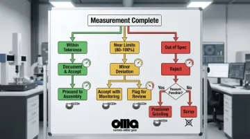
For gears with heat-treat distortion, precision grinding can often salvage parts that would otherwise be scrapped. Carnes-Miller Gear specializes in this type of corrective grinding, achieving AGMA 13 ratings on ground gears and recovering heat-treated parts that exceed tolerance.
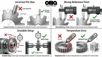
Common Errors in Gear Tooth Profile Measurement
Measurement errors often exceed actual gear manufacturing errors, leading to incorrect acceptance or rejection decisions. Understanding these pitfalls ensures reliable quality control.
Incorrect Pin or Tool Sizing
Using wrong pin diameter in over-pins method causes measurement at incorrect point on tooth flank, leading to false readings that don't reflect actual tooth thickness.
The problem:
- Pins too small contact near tooth root (reads thick)
- Pins too large contact near tip (reads thin)
- Calculations must account for actual pin size used, not just ideal size
Measurement at Wrong Reference Point
Measuring chordal thickness at incorrect depth (wrong chordal addendum calculation) gives meaningless results that cannot be compared to specifications.
Common reference point errors include:
- Span measurements over wrong number of teeth produce incomparable data
- Over-pins measurements require diametrically opposite positions for even-tooth gears
- Chordal addendum miscalculations invalidate thickness readings
Unstable Workpiece or Inadequate Fixturing
Beyond measurement point selection, physical setup issues dramatically affect accuracy.
Fixturing and stability problems:
- Gear runout, wobble, or movement introduces errors larger than actual profile variations
- Temperature variations cause dimensional changes—a 500mm gear measured at 25°C (5°C delta) shows approximately 29 µm dimensional error
- Dirty or damaged tooth surfaces prevent proper tool contact
- Inadequate clamping allows workpiece movement during measurement
Misreading Measurement Instruments
Even with proper setup, operator errors compromise results.
Common instrument mistakes:
- Reading dial indicators in wrong direction
- Parallax errors on vernier scales
- Inconsistent measuring pressure with micrometers
- Failing to zero instruments properly
Best practice: Average multiple measurements correctly by identifying and investigating outliers rather than simply including them in the calculation.
Safety and Best Practices
Gear measurement errors often trace back to contaminated surfaces, unstable temperatures, or improper handling—all preventable with disciplined practices.
Personal Safety and Work Area
Essential safety measures:
- Ensure adequate lighting to see measurement scales and tooth surfaces clearly
- Maintain clean work area free of oil and debris that could cause slips or contaminate measurements
- Wear safety glasses when handling gears, especially when cleaning with compressed air or solvents
- Use proper lifting techniques for heavy gears to prevent back injury
Beyond personal safety, measurement accuracy demands equally strict protocols.
Measurement Accuracy Practices
Critical practices for reliable results:
- Remove all chips, oil, and dirt from tooth surfaces and measurement tools before measuring
- Allow gears and tools to stabilize to room temperature (minimum 2 hours for large gears)
- Verify calibration status of all measurement instruments before use per ISO/IEC 17025 and AGMA 931-A02 standards
- Use light, consistent measuring pressure, especially with micrometers equipped with ratchet stops
- Take measurements at multiple positions and investigate any outliers before averaging
- Record measurement conditions (temperature, tools used, operator) for traceability
Conclusion
Accurate gear tooth profile measurement is essential for ensuring gear quality, preventing premature failures, and maintaining system performance in critical applications.
Success requires selecting appropriate measurement methods, using calibrated tools, avoiding common errors, and correctly interpreting results—separating effective quality control from guesswork.
When measurements indicate borderline or out-of-spec conditions, partnering with experienced gear manufacturers who understand both measurement techniques and manufacturing capabilities helps determine the best path forward.
Carnes-Miller Gear provides comprehensive grinding services up to 400mm diameter and achieves AGMA 13 ratings on ground gears. With over 50 years of precision manufacturing experience, the company combines manufacturing expertise with quality verification capabilities for aerospace, defense, medical, and industrial applications.
Frequently Asked Questions
What is the clearance between the tooth profiles of a gear tooth?
Clearance is the radial distance between the top of one gear tooth and the bottom of the mating tooth space when properly meshed. For standard gears, clearance equals 0.157 times the module to prevent interference and allow lubrication.
What is the difference between tooth thickness and tooth profile measurement?
Tooth thickness measures the width of the tooth (as arc length or chord), while profile measurement verifies the involute curve shape. Both are necessary—correct thickness with incorrect profile still causes mesh problems, noise, and premature wear.
How accurate do gear tooth profile measurements need to be?
Requirements depend on AGMA quality grade—Grade A11 for commercial gears to Grade A2 for aerospace. Tolerance bands range from ±0.003" for lower grades to ±0.0002" for precision applications.
What causes errors in gear tooth profile measurements?
Common causes include incorrect tool sizing or positioning, temperature variations (even 1°C causes expansion), workpiece runout, contaminated tooth surfaces, and operator technique inconsistencies.
Can gear tooth profiles be measured without specialized equipment?
Basic tooth thickness can be verified with standard micrometers and calculated pins, but true involute profile verification requires specialized gear analyzers or CMM equipment. Professional gear inspection services provide the most reliable results for critical applications.
What are AGMA quality grades and how do they relate to profile measurements?
AGMA quality grades (numbered A2-A11 in current AGMA 2015 standards) define tolerance bands for various gear parameters including profile accuracy, with lower numbers indicating tighter tolerances. Profile measurements must fall within the specified grade's tolerance to meet application requirements.