Introduction
A single micron of error in gear tooth profile geometry can mean the difference between smooth operation and premature failure in aerospace gearboxes or medical devices. Profile deviations as small as 0.0005" correlate directly with transmission error, causing vibration, noise, and accelerated wear.
The challenge intensifies in applications like electric vehicles, where gear whine—once masked by combustion engines—now stands out prominently. For quality engineers and gear manufacturers, the question isn't whether to inspect profiles, but how to do so accurately and efficiently.
This guide covers the inspection methods precision manufacturers rely on to verify tooth profile accuracy against AGMA and ISO standards:
- Coordinate measuring machine (CMM) procedures for profile evaluation
- Gear analyzer selection and setup for production environments
- Interpreting profile deviation charts and tolerance bands
- Best practices for validating ground gears to AGMA 13 specifications
Whether you're verifying ground spur gears or troubleshooting noise issues in gear assemblies, these methods ensure your components meet the exacting micro-geometry requirements critical applications demand.
Key Takeaways
- CMMs deliver highest precision (±0.0001" possible) for critical first-article inspection and aerospace applications
- Optical systems capture up to 12 million measurement points for rapid non-contact surface analysis
- ISO 1328-1 tolerance classes (1-11) guide acceptance criteria for profile deviations like $F_α$ and $f_{fα}$
- Temperature control at 68°F ±2°F is mandatory—steel expands 0.0000063"/inch/°F, exceeding tight tolerances quickly
- Distinguish intentional modifications (tip relief, crowning) from manufacturing errors to avoid false rejections
What You Need for Gear Tooth Profile Inspection
Measurement Equipment Options
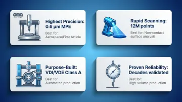
Primary inspection technologies include:
- Coordinate Measuring Machines (CMMs): Achieve MPE as low as 0.6 µm with certified algorithms for cylindrical, bevel, and worm gears
- Optical measurement systems: Capture up to 12 million points per scan with 2-56 µm accuracy depending on field of view
- Gear measuring machines (GMMs): Purpose-built systems meeting VDI/VDE 2612 Class A standards with automated 20-minute run times
- Mechanical profile checkers: Stylus-based systems with dial indicators, proven for decades in production environments
Environmental and Setup Requirements
Precision metrology demands rigorous environmental control. Without proper conditions, even the best equipment produces unreliable results.
Key environmental factors:
- Temperature stability at 20°C (68°F) per ISO 1, with ±2°F variation maximum and spatial gradients below 1 K/m
- Anti-vibration mounts or isolated foundations to prevent measurement noise
- Controlled lighting to avoid optical interference from reflections
- Adequate soak time for workpieces to reach thermal equilibrium before measurement
Supporting Tools and Fixtures
Essential accessories include:
- Precision centers or mandrels for secure, deformation-free mounting
- Datum establishment tools for axis alignment
- Cleaning supplies to remove chips, coolant, and oils that cause false readings
- Gear inspection software with certified involute algorithms
- Master gears or calibration artifacts for verification
Methods to Inspect Gear Tooth Profile
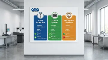
Quality control teams rely on three primary inspection methods, each suited to different scenarios. Coordinate measurement delivers ultimate accuracy, optical scanning provides speed and non-contact verification, and mechanical checking serves high-volume production environments.
Method 1: Coordinate Measuring Machine (CMM) Inspection
Description: CMMs use precision probes to collect 3D coordinate points across tooth flanks, comparing measured profiles to theoretical involute curves with sub-micron accuracy. This method represents the gold standard for gear inspection when absolute precision matters most.
Tools/Indicators Needed:
- CMM with rotary table (handles up to 3-meter diameter gears)
- Touch-trigger or continuous scanning probe
- Certified gear inspection software with involute calculation accuracy <0.1 µm
- Temperature-controlled environment at 68°F ±2°F
Step-by-Step Process:
- Mount and align: Secure gear on rotary table, establishing datum axis from functional surfaces (bore or face, never worn centers)
- Program probe path: Configure CMM to follow theoretical involute path from below profile control diameter through tip break, per ISO 1328-1 requirements
- Collect data: Capture minimum 150 points approximately equally spaced along roll length across 4-8 teeth for statistical validity
- Calculate deviations: Software computes total profile deviation ($F_α$), profile form deviation ($f_{fα}$), and slope deviation ($f_{Hα}$)
- Generate reports: Produce profile deviation charts showing measured trace against design profile with tolerance bands

Pros & Cons:
Advantages: Delivers the highest accuracy achievable (±0.0001" or 0.6 µm MPE). Excellent for first article inspection and quality audits. Results trace directly to national metrology standards. Handles complex geometries including bevel and worm gears.
Limitations: This is the slowest method—expect 15-30 minutes per gear, up to an hour for comprehensive topography. Equipment investment runs high. You'll need skilled operators and strict climate control. The contact method may leave marks on soft materials.
Method 2: Optical Measurement Systems
Description: This non-contact method uses laser triangulation or structured light to capture tooth surface geometry, creating 3D models with millions of measurement points. The approach eliminates surface damage concerns while dramatically reducing inspection time.
Tools/Indicators Needed:
- Laser scanner or structured-light scanner (12 million point capacity)
- Precision rotary indexer for controlled positioning
- Optical measurement software for 3D reconstruction
- Controlled lighting environment to prevent interference
Step-by-Step Process:
- Surface preparation: Thoroughly clean gear to ensure proper light reflection; matte surfaces may require light coating
- Mount and align: Position gear on indexer with axis alignment verified
- Capture surface data: Scanner projects light pattern or laser line onto flanks; cameras capture reflected pattern from multiple angles
- Reconstruct 3D model: Software processes captured images into comprehensive surface model
- Compare to design: Measured surface compared to CAD model, identifying profile deviations across entire flank area
- Extract compliance data: Software extracts specific line traces from 3D cloud for ISO 1328-1 parameter calculation
Pros & Cons:
Advantages: Completes measurement in 5-10 minutes. Non-contact operation prevents damage to soft materials or thin-walled gears. High-resolution surface mapping reveals defects tactile probes miss. Ideal for process control with rapid feedback.
Limitations: Accuracy runs slightly lower than CMM (±0.0005" or 2-56 µm depending on system). Sensitive to surface finish and reflectivity—highly polished or dark surfaces can pose challenges. Deep narrow tooth spaces may prove difficult to access. Requires data extraction for standard compliance.
While optical systems offer speed, traditional mechanical methods remain valuable in many production settings.
Method 3: Mechanical Profile Checkers and Gear Rolling Testers
Description: This traditional method uses stylus contact or master gear meshing to evaluate profile accuracy through direct measurement or composite action testing. Decades of industry validation make it a trusted approach for production inspection.
Tools/Indicators Needed:
- Gear measuring machine with profile stylus
- Precision master gear for rolling tests (Class 1-2 accuracy)
- Dial indicators or electronic transducers
- Chart recorder or digital display for deviation tracking
Step-by-Step Process:
Profile checking approach:
- Mount gear and align datum axis with measurement axis
- Position stylus at start of active profile (below control diameter)
- Guide stylus along theoretical involute path while recording deviations
- Repeat for multiple teeth (minimum 4) to establish pattern and tooth-to-tooth variation
Rolling test approach:
- Mesh test gear with precision master gear under light, consistent load
- Rotate gears together while monitoring center distance variation (double-flank) or angular position variation (single-flank)
- Record deviations indicating composite profile and spacing errors
- Analyze patterns to identify specific error types
Pros & Cons:
Advantages: Decades of industry validation prove this method's reliability. Equipment costs run lower than CMM systems. Effective for production inspection and process control. Rolling tests quickly identify functional issues affecting mesh quality. Meets VDI/VDE 2612 Class A standards.
Limitations: Contact method may mark soft materials or leave witness marks. Resolution runs lower than CMM—fine surface details may be missed. Rolling tests show composite error, making it impossible to isolate profile from spacing or runout. Interpreting chart recordings requires operator skill. Inspection takes longer than optical methods.
How to Interpret the Results
Proper interpretation requires understanding the difference between manufacturing errors and intentional modifications (tip relief, crowning), plus knowing tolerance standards for the application.
Misinterpretation has consequences: accepting out-of-tolerance gears leads to premature failure, noise, and reduced load capacity, while rejecting acceptable gears with intentional modifications wastes resources.
Normal/Acceptable Profile Characteristics
Correct measurements show specific patterns within defined tolerance bands:
Profile characteristics:
- Smooth involute curve within tolerance band (±0.0005" to ±0.002" depending on ISO 1328-1 class)
- Intentional tip relief showing gradual material removal near tip (0.0005"-0.003" typical depth)
- Possible profile crowning with slight convexity at pitch line for load centering
- Uniform pattern across all measured teeth with minimal tooth-to-tooth variation
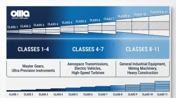
ISO 1328-1 tolerance classes (adopted as ANSI/AGMA ISO 1328-1) define 11 grades numbered 1-11, where Class 1 represents highest precision:
- Master gears and ultra-precision reference standards (Classes 1-4)
- Aerospace, high-speed turbines, EV transmissions requiring minimal noise and vibration (Classes 4-7)
- General industrial machinery and lower-speed applications (Classes 8-11)
Next actions:
- Document measurements for quality records and traceability
- Compare to previous inspection data to track process stability and identify trends
- Release part for next manufacturing operation or final assembly
- Archive data for customer review and future reference
Minor Deviations and Acceptable Tolerance
Slight variations within acceptable limits don't compromise function:
- Small localized bumps or dips (±0.0003") from tool chatter
- Minor slope variation not exceeding $f_{Hα}$ limit for specified class
- Tooth-to-tooth variation within cumulative pitch tolerance
- Edge effects at profile start/end outside evaluation range
Tolerance determination: Each ISO class defines specific limits for $F_α$ (total profile deviation), $f_{fα}$ (form deviation), and $f_{Hα}$ (slope deviation) based on module and face width.
A Class 5 gear has tighter limits than Class 8 for the same dimensions.
What to do:
- Monitor trend across production run—increasing deviations signal tooling wear or process drift
- Perform contact pattern simulation to verify deviation doesn't affect load distribution
- Document for customer review if approaching tolerance limit
- Investigate if consecutive parts show similar deviations (systematic issue)
Out-of-Spec Profile Conditions
Critical errors requiring immediate action:
Error types and causes:
- Involute form error exceeding tolerance: Indicates cutting tool wear, incorrect tool geometry, machine accuracy issues, or heat treat distortion
- Profile hollow at pitch line: Creates stress concentration and noise; caused by improper hob relief, grinding wheel dressing errors, or thermal distortion
- Excessive slope deviation ($f_{Hα}$): Profile "leans" wrong direction; results from incorrect pressure angle, machine setup error, or fixture misalignment
- Asymmetric deviations: Different patterns on opposite flanks suggest mounting problems, datum errors, or spindle runout
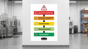
Immediate actions:
- Quarantine immediately: Segregate out-of-spec parts to prevent shipment or assembly
- Root cause investigation: Determine if error stems from tooling, machine calibration, heat treat process, or fixturing issues
- Corrective action: Implement fixes before continuing production—replace worn tools, recalibrate equipment, adjust heat treat parameters, improve fixturing
- Salvage assessment: Determine if grinding or other finishing operations can bring parts into tolerance if sufficient stock allowance remains
- Documentation: Record nonconformance details, root cause, corrective action, and verification for quality system compliance
Common Errors in Gear Tooth Profile Inspection
Inspection errors lead to false acceptance of bad parts or false rejection of good parts—both costly outcomes that undermine quality systems and customer confidence.
Fixturing and Datum Errors
Improper mounting creates misalignment between measurement axis and actual gear axis, causing false profile deviations that don't exist in the gear itself.
Common mistakes:
- Worn or damaged centers/mandrels introduce runout into measurements
- Insufficient clamping pressure allows part movement during measurement
- Datum established from non-functional surfaces instead of bore or mounting face
- Ignoring runout of mounting surfaces before measurement
- Elastic deformation from over-clamping thin-walled gears
- Contamination (chips, burrs) on datum surfaces preventing proper seating
Datum axis misalignment corrupts all profile measurements. A 0.001" runout at the mounting surface translates directly into false profile errors of similar magnitude.
Environmental and Equipment Factors
Beyond fixturing, environmental conditions and equipment maintenance directly affect measurement accuracy.
Temperature effects: Steel expands/contracts 0.0000063" per inch per °F. A 10°F temperature difference on a 10-inch gear causes 0.00063" dimensional change—exceeding tolerance for precision gears requiring Class 7 or tighter (aerospace, EV applications). Measurements away from 68°F reference without compensation yield incorrect data.
Other environmental factors:
- Vibration: Introduces noise in sensitive measurements, particularly affecting CMM and optical systems
- Contamination: Chips, coolant, oils on tooth flanks measured as positive material (false bumps), skewing form deviation
- Humidity: Condensation on optical components degrades measurement accuracy
- Air currents: Affect optical systems and can cause temperature gradients
Equipment maintenance directly impacts data quality. Uncalibrated instruments produce systematic errors, while worn stylus tips increase effective probe radius and distort measurements. Dirty optical components reduce capture quality, and incorrect software parameters (wrong base circle or pressure angle input) corrupt theoretical profile calculations.
Measurement Technique and Interpretation Mistakes
Operator errors degrade results even with properly functioning equipment:
Common mistakes:
- Measuring wrong portion: Collecting data outside active profile (below root or above tip break) includes non-functional areas
- Confusing modifications with errors: Rejecting gears with properly executed tip relief or crowning because they deviate from perfect involute
- Inadequate sampling: Measuring too few teeth (fewer than 4) misses tooth-to-tooth patterns and statistical validity
- Incorrect software parameters: Wrong module, pressure angle, or helix angle inputs corrupt theoretical profile calculation
- Not accounting for coatings: Specified coating thickness adds material; measuring coated parts against uncoated design profile shows false positive deviation
- Ignoring soak time: Measuring parts before thermal stabilization captures thermal expansion, not actual geometry
Safety and Best Practices
Gear inspection involves precision equipment, heavy workpieces, and controlled environments that demand specific safety protocols. Following these best practices protects operators, preserves measurement accuracy, and prevents damage to expensive gears and instruments.
Equipment Safety and Lockout
Required precautions:
- Ground all gear measuring machines and CMMs properly to prevent electrical hazards
- Follow lockout/tagout procedures when changing fixtures, probes, or performing maintenance
- Use proper lifting techniques or mechanical assistance (hoists, carts) for heavy gears—many exceed 50 lbs
- Secure gear properly with adequate clamping force to prevent falling during measurement or rotary table indexing
- Be aware of pinch points on rotary tables, indexers, and moving axes
- Maintain clear workspace around equipment to prevent tripping hazards
- Never bypass safety interlocks or protective enclosures
Measurement Environment Control
Temperature fluctuations and environmental conditions directly affect measurement accuracy. Precision inspection requires strict control.
Best practices for accuracy:
- Maintain temperature at 68°F ±2°F (20°C ±1°C) for precision work requiring Class 7 or tighter
- Allow gears to stabilize to room temperature before measuring (typically 1-4 hours depending on mass)
- Minimize air currents from HVAC vents, doors, or personnel movement that create thermal gradients
- Use anti-vibration mounts for sensitive equipment; isolate from production floor vibration
- Control humidity between 40-60% to prevent condensation on optical components and corrosion on precision surfaces
- Monitor and log environmental conditions during critical measurements for traceability
Handling and Cleanliness Protocols
Procedures to prevent contamination and damage:
- Wear lint-free gloves to prevent fingerprints and skin oils that attract contaminants and affect optical measurements
- Thoroughly clean gears before inspection using appropriate solvents (avoid residues that affect measurements)
- Inspect for burrs and remove carefully with deburring tools before measurement (burrs measured as material create false readings)
- Store master gears and calibration standards in protective cases with desiccant in climate-controlled environment
- Never force parts onto fixtures—investigate and correct any fitment issues (forcing induces stress and misalignment)
- Clean stylus tips regularly per manufacturer recommendations (contamination increases effective tip radius)
- Handle gears by non-functional surfaces when possible to avoid damaging critical tooth flanks
Conclusion
Accurate gear tooth profile inspection is essential for ensuring performance, longevity, and quiet operation in critical applications from aerospace to industrial machinery.
Selecting the appropriate inspection method prevents costly failures and customer returns:
- CMM systems for precision first-article work and aerospace applications requiring Class 4-7 tolerances
- Optical systems for rapid process control and comprehensive surface analysis
- Mechanical checkers for high-volume production environments
Proper interpretation against ISO 1328-1 standards ensures measurements translate into actionable quality decisions.
Systematic inspection procedures require environmental controls—68°F ±2°F temperature stability, vibration isolation, and contamination prevention—paired with skilled interpretation that distinguishes intentional profile modifications from manufacturing errors.
Carnes-Miller Gear applies these rigorous inspection protocols across aerospace, defense, and medical manufacturing, validating that ground gears achieve AGMA 13 ratings and shaped/hobbed gears meet AGMA 10 standards. This combination of precise measurement and expert interpretation delivers the reliability customers demand in precision-critical applications.
Frequently Asked Questions
What is the difference between profile deviation and lead deviation in gear inspection?
Profile deviation measures involute curve accuracy in the radial direction (root to tip), evaluating form and slope errors. Lead deviation measures tooth alignment in the axial direction (across face width), detecting helix angle errors and twist.
How often should gear tooth profiles be inspected during production?
First article inspection verifies setup before production begins. Inspection frequency depends on volume and capability—typically every 25-50 parts for critical applications (aerospace, defense, medical), plus after tool changes or setup adjustments.
Can heat treatment distortion be corrected after inspection reveals profile errors?
Gears with heat treat distortion can often be salvaged through grinding if sufficient stock allowance (0.010"-0.030" typical) was left before heat treatment. Severe distortion exceeding grinding capacity renders parts unusable.
What ISO 1328-1 quality class is required for different applications?
Industrial and mining applications typically use Classes 8-10, precision industrial and automotive use Classes 7-9, while aerospace, defense, and high-speed turbines require Classes 4-7. Tighter classes demand CMM accuracy, while Classes 8-10 can be verified with mechanical checkers.
Why is temperature control critical during gear inspection?
Steel expands/contracts approximately 0.0000063 inches per inch per degree Fahrenheit. A 10°F difference on a 10-inch gear causes 0.00063" dimensional change, which exceeds Class 7 tolerances. ISO 1 mandates 20°C (68°F) as the standard reference temperature.
What is the difference between single-flank and double-flank composite testing?
Single-flank testing monitors angular position variation with one flank in contact, revealing profile form deviations and pitch errors. Double-flank testing monitors center distance variation with both flanks in contact, primarily revealing runout and radial errors.