
Introduction
Gear reverse engineering is the systematic process of recreating gear specifications, geometry, and manufacturing parameters from existing physical samples when original drawings or documentation are unavailable.
For maintenance engineers, OEMs, gear manufacturers, and industrial operations managers working with legacy equipment, obsolete machinery, or undocumented gear systems, reverse engineering is critical for reducing downtime, maintaining operations, and avoiding costly equipment replacement.
The financial stakes are substantial. Recent data reveals that 61% of manufacturers experienced unplanned downtime in the past year, with costs reaching as high as $1.7 million per hour in automotive and heavy industrial sectors. For process industries, average downtime costs range from $125,000 per hour to over $500,000 per hour depending on operation scale.
Basic gear measurement is commonly discussed, but advanced reverse engineering techniques involving precision measurement technologies, material analysis, and complex geometry recreation are often poorly understood in practice. These advanced techniques become essential when downtime costs demand speed and accuracy beyond what manual methods can deliver.
This article explains:
- What distinguishes advanced reverse engineering from basic measurement
- Step-by-step methodology using modern technologies
- Factors affecting accuracy
- When different techniques are appropriate
Key Takeaways
- Recreates gear specifications from physical samples when original documentation is missing
- CMM systems and 3D laser scanning replace traditional measurement tools for precision
- Key parameters: tooth count, pitch, pressure angle, material composition, heat treatment
- Requires excellent gear condition and precise documentation of profile modifications
- Serves industrial, mining, power generation, marine, and aging equipment sectors
What Is Gear Reverse Engineering?
Gear reverse engineering determines all manufacturing specifications of an existing gear when original drawings are unavailable. The process uses measurement, analysis, and calculation to capture dimensional parameters, material properties, and geometric characteristics.
The outcome is complete technical documentation that enables precise replication:
- Engineering drawings with full dimensional specifications
- Material specifications and heat treatment requirements
- Manufacturing instructions for production
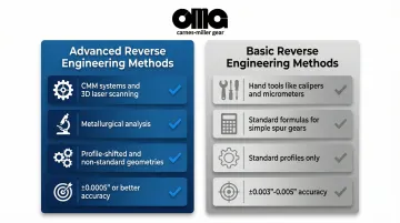
Advanced vs. Basic Reverse Engineering
| Feature | Advanced Methods | Basic Methods |
|---|---|---|
| Equipment | CMM systems, 3D laser scanning | Hand tools (calipers, micrometers, pitch gauges) |
| Analysis | Metallurgical analysis, complex calculations | Standard formulas for simple spur gears |
| Gear Types | Profile-shifted, non-standard geometries | Standard profiles only |
| Accuracy | ±0.0005" or better | ±0.003"-0.005" |
Why Gear Reverse Engineering Is Used in Industrial Applications
Industrial facilities commonly face situations where critical gears fail in equipment that is 20-50+ years old. Original manufacturers are out of business, documentation has been lost, or OEM replacement parts are no longer available.
When parts are available, they're often extremely expensive with long lead times.
The Legacy Equipment Crisis
The scale of this challenge is significant:
- The average age of the North American nuclear fleet is approximately 35 years, with many components exceeding 50 years of service
- 20-25% of components in these plants are no longer supported by the original manufacturer
- Standard lead times for critical parts now range from 12 to 30 weeks, with complex legacy parts taking up to 12 months
What Reverse Engineering Addresses
These constraints force facilities to find alternatives. Reverse engineering provides three critical solutions:
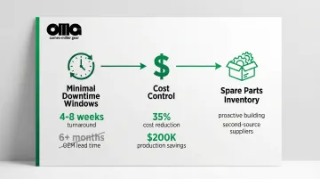
Minimal Downtime Windows
- Typical maintenance windows: 2-4 weeks
- OEM lead times: 6+ months for obsolete equipment
- Reverse engineering turnaround: 4-8 weeks
Cost Control
- Specialized manufacturers have achieved 35% cost reduction through optimized gear machining processes
- In one case, a $3,000 reverse-engineered part (vs. $300 standard) saved $200,000 in lost production by reducing lead time from 12 weeks to 3 weeks
Spare Parts Inventory Creation
- Proactive inventory building before failure
- Second-source supplier establishment
- Elimination of single-vendor dependency
Reverse engineering has become industry best practice for maintenance of legacy equipment and is often operationally preferred over complete equipment replacement when the gear drive is mechanically sound except for one failed component.
How Advanced Gear Reverse Engineering Works
Gear reverse engineering transforms a physical component into complete manufacturing specifications through systematic analysis. The process captures dimensional data, determines material composition, and recreates production-ready CAD models.
This technique proves essential for replacing obsolete parts where original documentation no longer exists.
What Goes Into the Process
Required Inputs:
- Physical gear sample (preferably unworn or with measurable wear documentation)
- Precision measurement equipment (CMM, 3D scanners, gear analyzers)
- Material testing capabilities
- Engineering expertise in gear geometry and manufacturing
- Specialized software for gear design calculations and CAD modeling
Core Transformation
Engineers convert raw measurement data into standardized gear parameters through mathematical formulas and reverse calculations. The transformation involves:
- Spectroscopy analysis identifies alloy composition from material samples
- Surface hardness testing determines heat treatment specifications
- Tooth geometry analysis detects profile modifications or non-standard designs
Process Control
Quality assurance throughout the process includes:
- Multiple measurement techniques to quantify and minimize uncertainty
- Verification of calculations against physical dimensions
- Cross-referencing material specifications with industry standards
- Prototype manufacturing and fit testing before final production
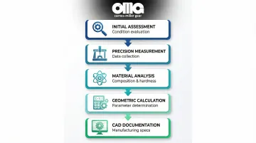
Step 1: Initial Assessment and Documentation
This step involves:
- Visual inspection to assess gear condition (wear patterns, damage, modifications)
- Photographic documentation from multiple angles
- Counting and recording basic parameters (number of teeth, approximate size, gear type)
- Determining whether the gear is suitable for reverse engineering or too worn to yield accurate measurements
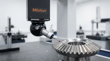
Step 2: Precision Measurement and Data Collection
Advanced measurement technologies capture precise gear geometry:
| Technology | Capabilities | Performance |
|---|---|---|
| Coordinate Measuring Machines (CMM) | Micron-level tooth profile accuracy | Volumetric error: 1.5 + L/333 µm Repeatability: 1.4 µm |
| 3D Laser Scanning | Complete surface geometry capture with millions of points | Point spacing: 30-120 µm 70% faster than tactile methods |
| Gear Analyzers | Pitch, spacing, helix angle, pressure angle verification | Essential for helical and bevel gears |
Step 3: Material and Heat Treatment Analysis
This step employs:
Optical Emission Spectroscopy (OES):
- Determines exact alloy composition including carbon content
- Essential for steel gears (XRF cannot detect carbon)
- Measures carbon, sulfur, phosphorus per ASTM E415
Hardness Testing:
- Rockwell or Brinell hardness testing across tooth surfaces and core
- Maps heat treatment patterns
- Verifies case depth for carburized or nitrided gears
Metallographic Examination:
- Verifies case depth and microstructure when needed
- Identifies heat treatment processes used
Step 4: Geometric Analysis and Calculation
Engineers use collected data with gear geometry formulas to:
- Calculate diametral pitch or module
- Verify pressure angle through measurement correlation
- Determine if profile shift or non-standard modifications were applied
- Calculate center distances for mating gear sets
- Reverse-engineer custom hub and keyway specifications
Step 5: CAD Modeling and Documentation Creation
The reverse engineering process produces complete manufacturing documentation:
- 3D CAD solid models using calculated parameters and measured geometry
- 2D engineering drawings with complete dimensioning and tolerancing per AGMA or ISO standards
- Documentation of material specifications and heat treatment requirements
- Manufacturing instructions including recommended machining sequences and quality control checkpoints
For manufacturers like Carnes-Miller Gear, these specifications enable precision reproduction of obsolete gears where original drawings no longer exist—critical for maintaining legacy equipment in aerospace, defense, and industrial applications.
Advanced Measurement Technologies and Techniques
Coordinate Measuring Machines (CMM)
CMM systems provide the highest accuracy for gear tooth profile measurement. Probe-based systems measure involute profile deviations within 5 microns.
These systems generate detailed reports on pitch variation, profile accuracy, and lead/helix deviations compared to theoretical geometry.
Verification standards:
- ISO 10360-2 for length measurement
- ISO 10360-4 for scanning probing error
3D Laser Scanning and Structured Light Systems
These systems capture complete gear geometry including worn areas, creating point cloud data that can be processed into CAD models. They work especially well for large gears or when multiple samples with varying wear need to be analyzed to determine original unworn dimensions.
Key advantages:
- A 3D scan captures 2.5 million points in 30 minutes
- Tactile probe captures only 300 points in 4 hours
- Desktop micro-scanners achieve 5 µm deviation
Gear Rolling Analyzers
These systems simulate gear meshing to measure cumulative pitch variation, runout, and tooth-to-tooth composite errors, providing functional performance data that supplements dimensional measurements.
Testing types:
- Double Flank Testing: Measures Total Composite Error (TCE) and Tooth-to-Tooth Error (TTE)
- Single Flank Testing: Simulates operation to measure transmission error and backlash
- Uses ISO 1328 and AGMA 2000/2015 standards
Material Analysis Techniques
| Feature | Handheld XRF | Optical Emission Spectroscopy (OES) |
|---|---|---|
| Primary Use | Rapid, non-destructive alloy sorting | Precise chemical composition & trace elements |
| Key Limitation | Cannot detect Carbon or Boron | Requires sample preparation |
| Steel Application | Cannot distinguish carbon steels | Essential for measuring carbon content |
| Standards | ASTM E415 | ASTM E415, ASTM E1086 |
For gear reverse engineering, OES is mandatory to determine carbon content for heat treatment specifications.
XRF is insufficient for steel gears as it cannot measure the carbon percentage that defines hardness and weldability.
Accuracy Comparison
| Measurement Method | Accuracy | Time Required | Best Application |
|---|---|---|---|
| Hand Tools | ±0.005" | 1-2 hours | Simple spur gears, non-critical |
| Precision Instruments | ±0.0005" | 3-4 hours | Standard gears, moderate precision |
| CMM Systems | ±0.0002" or better | 4-6 hours | Complex gears, high precision |
| 3D Scanning | ±0.0001"-0.004" | 0.5-1 hour | Large gears, worn samples |
Where Gear Reverse Engineering Is Applied
Types of Equipment
Reverse engineering is commonly needed for:
- Legacy industrial machinery with 30+ year service life
- Imported equipment where OEM support is unavailable in the US
- Custom or one-off gear drives with no surviving documentation
- Military or marine applications requiring exact obsolete replacements
- Mining equipment in remote locations where lead times are critical
Equipment Lifecycle Points
The need for reverse engineering typically arises at specific points in equipment operation:
- During planned maintenance outages when worn gears are discovered
- After catastrophic gear failures requiring emergency replacement
- As part of preventive maintenance programs to build spare parts inventory before failure
- During equipment modernization projects where upgraded gears are designed based on existing geometry
Typical Triggers
Beyond scheduled maintenance, several warning signs trigger reverse engineering projects:
- Discovery of excessive noise or vibration indicating gear wear
- Scheduled inspection revealing tooth damage or pitting
- Failure of mating equipment that damages gears
- Strategic decisions to establish second-source suppliers for critical spare parts
Application Frequency
Facilities approach reverse engineering with different strategies:
- One-time: Emergency replacement after unexpected failure
- Periodic: Building spare parts inventory over time
- Systematic: Documenting critical gears as part of asset management
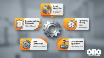
Key Factors That Affect Gear Reverse Engineering Accuracy
Successfully reverse engineering a gear requires understanding multiple variables that impact measurement accuracy. From the physical condition of the sample gear to the precision of your measurement equipment, each factor introduces potential error that compounds throughout the process.
Input Condition Factors
The gear's physical state directly affects measurement reliability:
- Gear wear: Worn gears may measure 0.010"-0.030" undersize on outside diameter
- Broken teeth or pitting can obscure original geometry
- Repairs or alterations may have changed original dimensions
Operating Environment and History
A gear's service history reveals critical information about dimensional changes:
- Temperature, loading, and contamination can cause dimensional changes
- Heat treat distortion may be present in the original gear
- Running-in wear patterns provide clues about manufacturing quality or misalignment
Measurement Equipment and Methodology
Your measurement approach determines the accuracy ceiling for the entire project:
- Equipment resolution varies significantly—hand tools provide baseline measurements while CMM and scanning systems deliver precision data
- Statistical sampling across multiple teeth yields more reliable data than single-point measurements
- Operator experience in gear metrology directly impacts measurement quality
- Proper fixture setup ensures measurement repeatability
Gear Complexity Factors
The gear's design characteristics introduce varying degrees of reverse engineering difficulty:
- Simple spur gears with standard profiles are straightforward, while helical or bevel gears with profile shift require advanced analysis
- Crowned teeth and load distribution modifications complicate profile measurement
- Integrated couplings or special hubs add modeling complexity
Documentation and Verification Requirements
Industry standards and application requirements define acceptable tolerances:
- Industry standards (AGMA, ISO, military specifications) govern accuracy requirements
- Prototype testing validates reverse-engineered designs before production
- Tolerance ranges vary from ±0.005" for general applications to ±0.0005" for precision work
With 50 years of experience, Carnes-Miller Gear applies this comprehensive understanding to reverse engineering projects, using CMM verification and AGMA 13-rated grinding capabilities to ensure accuracy for aerospace, defense, and medical applications.
Common Issues and Misconceptions
"Basic Hand Tools Are Sufficient"
Hand tools work for simple standard spur gears in non-critical applications, but they introduce serious limitations:
- Cumulative measurement errors of 0.003"-0.010" (unacceptable for high-speed or high-load applications)
- Cannot detect profile modifications
- Unable to measure complex gear geometries accurately
"Measuring OD and Counting Teeth Is Reverse Engineering"
This approach captures only 2 of 15+ critical parameters. Critical missing information includes:
- Pressure angle verification
- Profile shift detection (makes OD calculations invalid)
- Material and heat treatment specifications
- Tooth thickness and backlash requirements
- Manufacturing quality standards
Worn gears will measure smaller on the outside diameter than the original specification. Engineers must use the number of teeth and center distance to calculate the theoretical pitch using the formula: OD = Pitch × (Teeth + 2) for spur gears, adjusting for wear.
"Gear Geometry Equals Complete System"
Reverse engineering the gear geometry is not the same as reverse engineering the complete gear system. Additional critical components include:
- Mating gear specifications
- Center distance requirements
- Alignment specifications
- Lubrication requirements
- Bearing selections
All system components must be documented for successful gear replacement.
"Worn Gears Cannot Be Reverse Engineered"
While heavily worn gears (>0.030" material loss) are challenging, experienced engineers can determine original dimensions through:
- Analyzing unworn areas near the tooth root
- Measuring mating gears
- Using center distance calculations
- Applying statistical methods across multiple worn teeth to estimate original geometry
When Gear Reverse Engineering May Not Be Appropriate
Reverse engineering delivers significant value in the right circumstances, but it's not always the optimal solution. Understanding when to pursue alternative approaches saves time and resources while ensuring you get the best outcome for your application.
When Simpler Solutions Exist
Before investing in reverse engineering, exhaust these more straightforward options:
- Original documentation is available: Check archives, third-party sources, or OEM records for existing drawings and specifications
- OEM parts remain in production: The original manufacturer still produces the exact component with acceptable lead time and pricing
- Standard catalog options fit: Stock gear manufacturers offer products that meet your application requirements without customization
- Similar designs already exist: Gear manufacturers may have comparable designs in their archives that require minimal modification
Many companies pursue reverse engineering without first conducting thorough research into existing solutions. A few calls to OEM suppliers or gear manufacturers often reveals that the "obsolete" part is actually still available or has a direct replacement.
Physical Limitations That Prevent Accurate Reverse Engineering
Some conditions make it impossible to capture the original geometry accurately:
- Wear over 50% of tooth depth obscures original profiles
- Previous repairs with welding or machining have altered critical dimensions
- Catastrophic failure destroyed the gear beyond dimensional recovery
- Only photographs exist without physical samples for measurement
- Corrosion or damage prevents accurate scanning of tooth geometry
In these scenarios, working from application requirements to design a new gear often produces better results than attempting to reconstruct destroyed geometry.
When Modern Alternatives Outperform Reverse Engineering
Consider redesign rather than replication when:
- Modern gear drives offer superior performance for the same application
- Combined reverse engineering and manufacturing costs exceed new equipment with warranty coverage
- Application requirements have changed, requiring different ratios or load capacities
- The gear operates within an integrated system where single-component replacement creates compatibility problems
For companies like Carnes-Miller Gear with full in-house capabilities, the decision often isn't about whether reverse engineering is possible—it's whether it's the right approach. With over 50 years of gear manufacturing experience, our team can evaluate whether replicating an obsolete design serves your needs better than engineering an improved solution.
Conclusion
Advanced gear reverse engineering combines precision measurement technologies—CMM, 3D scanning, and material analysis—with engineering expertise to recreate complete manufacturing specifications from physical samples.
This systematic process enables replacement of worn or obsolete gears when original documentation is unavailable, addressing the critical challenge faced by facilities operating legacy equipment.
The distinction between basic measurement and advanced reverse engineering directly impacts equipment reliability, operational safety, and project success. Accuracy matters.
Selecting techniques based on gear complexity, application criticality, and required precision prevents costly failures and repeated rework.
Key considerations when deciding on reverse engineering:
- Assess gear condition and failure mode before committing
- Match measurement capabilities to precision requirements
- Verify specifications through proper quality control
- Evaluate alternatives: original parts, catalog gears, or system upgrades may prove more cost-effective
For organizations maintaining aging equipment where downtime costs can reach $125,000-$1.7 million per hour, advanced reverse engineering provides a strategic capability to maintain operational continuity while managing costs and lead times effectively.
Frequently Asked Questions
What are the 5 steps of reverse engineering a gear?
The five steps are: (1) Initial assessment and documentation, (2) Precision measurement using CMM or advanced tools, (3) Material and heat treatment analysis, (4) Geometric calculations for pitch, pressure angle, and profile modifications, and (5) CAD modeling with complete manufacturing specifications.
What tools are needed for accurate gear reverse engineering?
Basic projects use gear pitch gauges, calipers, micrometers, and protractors. Advanced work requires CMM systems, 3D scanners, gear rolling analyzers, hardness testers, and material analysis equipment (XRF or optical emission spectrometers).
How do you determine the pressure angle of a gear during reverse engineering?
Pressure angle is determined by measuring tooth profile with CMM or optical comparators and comparing against standard angles (14.5°, 20°, 25°), using pressure angle gauges that fit the tooth space, or calculating from center distance when mating gear specs are known.
Can worn gears be accurately reverse engineered?
Moderately worn gears (up to 0.020"-0.030" loss) can be reverse engineered by measuring unworn areas near the root and extrapolating dimensions using geometry relationships. Heavily worn gears require assumptions that may need prototype testing for verification.
Is reverse engineering of gears legal in the United States?
Creating replacement parts for equipment you own is generally legal in the United States, especially since patents expire after 20 years. However, reproducing parts for resale or copying newer proprietary designs may have restrictions requiring consultation with IP attorneys.
What is the difference between basic and advanced gear reverse engineering techniques?
Basic techniques use hand tools and standard formulas for simple spur gears in non-critical applications (±0.003"-0.005" accuracy). Advanced techniques employ CMM, 3D scanning, and material analysis for complex gears requiring ±0.0005" accuracy with complete heat treatment documentation.