Introduction
When heavy machinery fails in aerospace, mining, or manufacturing operations, the wrong gear choice is often to blame. Premature failure, excessive downtime, and costly replacements drain resources—major manufacturers face estimated losses of $59 million annually per plant, while automotive operations lose $2.3 million per hour during unplanned shutdowns.
Selecting the right industrial gear type ensures efficiency, longevity, and reliable performance across demanding applications. This guide examines nine essential gear types, their specific applications, and the engineering considerations that determine optimal selection for power transmission systems.
Key Takeaways
- Industrial gears transfer torque and change speed through meshing teeth designed for heavy loads and continuous operation
- Spur, helical, bevel, worm, double helical, internal, rack and pinion, planetary, and hypoid—nine types each serve distinct purposes
- Shaft configuration, torque, noise tolerance, efficiency, and space all drive selection
- Proper matching of gear type to application directly impacts equipment reliability and total cost of ownership
- Expect efficiency trade-offs from 50-98% depending on type, load capacity, and noise requirements
What Are Industrial Gears?
Selecting the wrong gear type can cost your operation thousands in downtime and repairs. Understanding the differences between industrial gear types ensures you specify components that match your mechanical requirements and operating conditions.
Industrial gears are precision-engineered rotating components featuring teeth (or cogs) that mesh with matching teeth on another gear to transmit mechanical power. Unlike consumer-grade gears, industrial versions withstand heavy loads, continuous operation, and harsh environments in sectors like mining, aerospace, defense, and heavy manufacturing.
Gears function as force multipliers—trading speed for torque or vice versa. This makes them essential for matching power sources to driven equipment requirements.
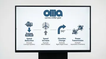
Key functions include:
- Converting high-speed motor output to low-speed, high-torque applications (crushers, conveyors)
- Increasing speed while reducing torque (spindles, turbines)
- Changing direction of rotational motion (bevel and worm gears)
- Transmitting power across varying distances and shaft orientations
Why Are Industrial Gears Important in Heavy Machinery?
Industrial gears are the backbone of heavy machinery, controlling speed and torque ratios that determine whether equipment operates at peak performance or falls short.
Properly selected gears improve energy efficiency by optimizing power transmission while reducing wear on connected components.
The Cost of Getting It Wrong
When gearing is inadequate or incorrectly specified, the consequences are both severe and costly:
- Premature tooth failure and accelerated wear
- Excessive vibration and noise generation
- Heat buildup and thermal damage
- Bearing and shaft damage from misalignment
- Production line shutdowns from unexpected failures
According to wind turbine maintenance studies, 25% of gearbox damage records in wind turbines involve the gears themselves, highlighting how critical proper gear selection and maintenance are to equipment reliability.
Types of Industrial Gears
Industrial gears come in nine primary configurations, each designed to handle distinct shaft arrangements, load profiles, and performance characteristics. Selecting the wrong gear type leads to premature failure, excessive noise, or inefficient power transmission.
Spur Gears
Description: Spur gears are the simplest and most common gear type, featuring straight teeth parallel to the gear axis on a cylindrical body.
How They Work: Teeth engage along their entire face width simultaneously, creating a single line of contact that transfers power between parallel shafts. This direct engagement makes them straightforward to manufacture and install.
Key Differences: Unlike helical or bevel gears, spur gears have no axial thrust and operate only on parallel shafts. They're the most straightforward to manufacture but generate more noise at high speeds due to sudden tooth engagement.
Best Suited For:
- Moderate-speed applications (under 20 m/s pitch-line velocity)
- Parallel shaft configurations
- Conveyors, machine tools, and gear pumps
- Applications where noise is not a critical concern
Key Strengths:
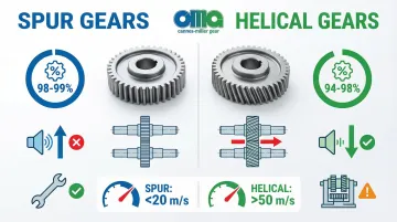
- Highest efficiency among gear types (98-99%)
- Simple design allows easy inspection and maintenance
- Cost-effective manufacturing
- Zero axial loads simplify bearing selection
- Imposes only radial loads on supporting structures
Limitations:
- Noisy operation at higher speeds due to sudden tooth engagement
- Limited load capacity compared to helical gears of similar size
- Not suitable for high-speed or quiet operation requirements
- Generally not recommended above 20 m/s (4000 fpm) pitch-line speed
Helical Gears
Description: Helical gears are cylindrical gears with teeth cut at an angle (helix angle, typically 15-30 degrees) to the gear axis, creating a diagonal tooth pattern.
How They Work: Angled teeth engage gradually rather than all at once, with multiple teeth in contact simultaneously. This creates smooth power transfer and distributes loads across several teeth, reducing stress concentrations.
Key Differences: The helix angle distinguishes them from spur gears and creates axial thrust that must be managed with appropriate thrust bearings. They operate much smoother and quieter than spur gears but are more involved to manufacture.
Best Suited For:
- High-speed applications (can operate above 50 m/s)
- Heavy-duty power transmission
- Situations requiring quiet operation
- Automotive transmissions, industrial gearboxes, and conveyor systems in mining and manufacturing
Key Strengths:
- Smooth, quiet operation even at high speeds
- Higher load capacity than equivalent spur gears due to increased contact ratio
- Gradual tooth engagement reduces shock loading and extends gear life
- Can handle speeds and loads that would make spur gears impractical
Limitations:
- Generate axial thrust that demands robust thrust bearings
- More expensive to manufacture than spur gears
- Sliding action between angled teeth creates slightly more friction, reducing efficiency to 94-98%
- Quality lubrication is essential to manage sliding contact
Double Helical Gears (Herringbone Gears)
Description: Double helical gears are two helical gears with opposite helix angles mounted side-by-side (or continuously formed) to create a distinctive V-shaped tooth pattern.
How They Work: The two opposing helix angles create thrust forces that cancel each other out, eliminating net axial load while maintaining all the benefits of helical tooth engagement. This self-balancing characteristic makes them ideal for high-load applications.
Key Differences: Combine the smooth operation of helical gears with the axial balance of spur gears. More intricate and expensive to manufacture than single helical gears but eliminate the need for heavy-duty thrust bearings.
Best Suited For:
- High-torque, high-speed applications
- Power generation (turbines, generators)
- Marine propulsion systems
- Heavy industrial mills
- Large gearboxes where reliability and load capacity are paramount
Key Strengths:
- Eliminates axial thrust while maintaining quiet, smooth operation
- Carries more load than any other parallel-shaft gear configuration
- Self-aligning properties reduce sensitivity to minor misalignment
- Can operate at high speeds with minimal vibration
Limitations:
- Most expensive parallel-shaft gear type to manufacture due to specialized machining
- Demands precise alignment during assembly
- Often needs a gap between helices for tool clearance (unless specialized continuous-tooth cutters are used)
- Limited availability from manufacturers due to specialized production requirements
Bevel Gears
Description: Bevel gears are cone-shaped gears with teeth cut on an angled surface, designed to transmit power between intersecting shafts (typically at 90 degrees).
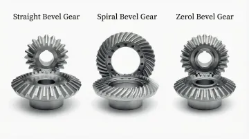
Variations: Three main types exist:
- Straight bevel: Straight teeth (simpler, noisier)
- Spiral bevel: Curved teeth (smoother, quieter)
- Zerol bevel: Curved teeth with zero spiral angle (compromise design)
Key Differences: Unlike cylindrical gears, bevel gears change the axis of rotation. Spiral bevel teeth engage gradually like helical gears, while straight bevel teeth engage suddenly like spur gears. Can achieve 98% or better efficiency when properly designed.
Best Suited For:
- Right-angle drives in heavy equipment
- Differential systems in vehicles
- Printing presses and marine propulsion
- Mining equipment and industrial machinery
- Any application needing power transfer between intersecting shafts
Key Strengths:
- Enable power transmission through angles (typically 90 degrees)
- Spiral bevel types offer smooth, quiet operation with high load capacity
- Versatile for various speed ratios
- Straight bevel types are more economical for lower-speed applications
Limitations:
- More expensive and involved to manufacture than parallel-shaft gears
- Demand precise mounting and alignment
- Straight bevel types are noisy at speeds above 10 m/s (2000 fpm)
- Limited to lower torque compared to same-sized parallel shaft arrangements
- Geometry defined by specialized standards (ISO 23509:2016)
Worm Gears
Description: Worm gears are a system pairing a screw-shaped worm (resembling a threaded shaft) with a worm wheel (a helical gear), operating on non-intersecting perpendicular shafts.
How They Work: The worm's threads engage the worm wheel's teeth in a sliding action, providing very high reduction ratios (10:1 to 500:1) in a compact package. Many designs offer inherent self-locking properties where the worm can drive the wheel, but the wheel cannot backdrive the worm.
Key Differences: Unique in providing extremely high gear ratios in a single stage. The sliding contact (rather than rolling) creates more friction and heat than other gear types. Self-locking behavior is valuable for safety-critical applications.
Best Suited For:
- Applications needing high reduction ratios in limited space
- Elevators and hoisting equipment (where self-locking prevents backdriving)
- Conveyor systems and tuning mechanisms
- Situations with heavy shock loading
- Applications needing smooth, constant output speed
Key Strengths:
- Achieves very high reduction ratios (up to 100:1 or more) in minimal space
- Smooth, quiet operation with constant output speed
- Self-locking property prevents reverse rotation (useful for safety applications)
- Handles shock loads well due to sliding engagement
- Compact right-angle configuration
Limitations:
- Lower efficiency (50-90%) due to sliding friction; efficiency drops significantly at higher ratios (can reach 50% at 300:1 ratios)
- Generates significant heat that demands cooling considerations—operating temperatures often rise 50°C (90°F) above ambient
- Uses different materials for worm and wheel (typically hardened steel worm, bronze wheel) to prevent galling
- Limited power transmission capacity compared to other types
- Needs specialized lubricants (compounded oils or PAG synthetics) to manage boundary lubrication

Rack and Pinion Gears
Description: Rack and pinion is a gear system pairing a circular pinion (spur or helical gear) with a linear rack (a straight bar with teeth), converting rotary motion to linear motion or vice versa.
How They Work: As the pinion rotates, its teeth engage the rack's teeth, moving the rack linearly. The linear distance traveled per pinion revolution depends on the pinion's pitch diameter. This simple mechanism provides precise position control.
Key Differences: Unlike other gears that transmit rotary motion, rack and pinion systems convert between rotary and linear motion. The rack can be conceptualized as a gear with infinite radius.
Best Suited For:
- Linear positioning systems and CNC machines
- Automotive steering systems
- Material handling equipment
- Any application needing precise conversion between rotational and linear movement
- Long-travel linear motion applications
Key Strengths:
- Provides precise, repeatable linear positioning
- Simple, cost-effective design
- Can achieve long linear travel distances by extending rack length
- Available in both spur (lower cost) and helical (smoother) configurations
- Easily scalable for different travel distances
Limitations:
- Backlash can affect positioning accuracy in precision applications
- Needs parallel mounting surfaces and precise alignment
- Pinion wear occurs faster than rack wear, needing periodic replacement
- Not suitable for applications with extremely high forces
- Quality grades (DIN 4 for metrology, DIN 6 for CNC) must be specified carefully
Internal Gears
Description: Internal gears are ring-shaped gears with teeth cut on the inside diameter, meshing with an external gear (pinion) that rotates inside the ring.
How They Work: The external pinion rotates inside the internal gear with both rotating in the same direction (unlike external gear pairs that rotate in opposite directions). This provides a compact, concentric shaft arrangement.
Key Differences: Teeth point inward rather than outward. Enables more compact designs than external gear pairs. Both gears rotate in the same direction rather than opposite directions, which is unique among simple gear pairs.
Best Suited For:
- Planetary gear systems (as the ring gear)
- Compact gearboxes needing concentric shafts
- Gear pumps and hydraulic motors
- Applications needing same-direction rotation
- Automatic transmissions and compact reduction drives
Key Strengths:
- More compact than external gear pairs for equivalent ratios
- Higher contact ratio distributes loads better, increasing capacity
- Enables epicyclic (planetary) gear arrangements with high power density
- Concentric shaft arrangement simplifies machine design
Limitations:
- More involved and expensive to manufacture than external gears
- Limited gear ratio range in simple pairs
- Needs specialized cutting tools and inspection methods
- Interference issues limit minimum tooth count differences between pinion and internal gear
- More difficult to inspect and measure than external gears
Planetary Gears (Epicyclic Gears)
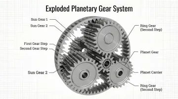
Description: Planetary gears are a system featuring a central sun gear, multiple planet gears that orbit around it (held by a carrier), and an outer ring gear (internal gear), all sharing a common axis.
How They Work: By holding different components stationary (sun, planet carrier, or ring), various speed ratios and directions can be achieved. Power splits across multiple planet gears, distributing loads and increasing capacity.
Key Differences: Unlike fixed-axis gears, planetary gears feature moving axes—planet gears orbit while rotating. Achieves high ratios in compact space by having multiple load paths. Enables sophisticated speed/torque configurations by controlling which element is fixed or driven.
Best Suited For:
- Automatic transmissions (multiple speed ratios)
- Heavy-duty industrial gearboxes
- Wind turbine drives
- Applications needing high power density
- Aerospace and robotics where weight and space are critical
- Applications with coaxial input/output shafts
Key Strengths:
- Highest power density (torque capacity per unit size/weight) among gear types
- Load sharing across multiple planets increases capacity and reliability
- Coaxial input/output shafts simplify machine design
- Can achieve wide range of ratios (typically 3:1 to 10:1 per stage, higher with multiple stages) by controlling which element is fixed
- Efficiency typically >95% for single stages
- Radial load cancellation on shafts when planets are properly balanced
Limitations:
- Most intricate and expensive gear system to design and manufacture
- Demands precise manufacturing and assembly to ensure equal load sharing among planets
- More components mean more potential failure points
- Planet bearings are critical components needing careful selection
- Optimal ratios typically fall between 3:1 and 10:1 per stage
Hypoid Gears
Description: Hypoid gears are specialized bevel-like gears where the pinion axis is offset from (does not intersect with) the gear axis, creating a hyperboloid tooth surface.
How They Work: Similar to spiral bevel gears but with axis offset allowing the pinion to be positioned below or above the gear centerline. The sliding contact along teeth provides smooth, quiet operation at the cost of some efficiency.
Key Differences: Unlike standard bevel gears where axes intersect, hypoid axes are skew (offset). This offset enables lower pinion placement (useful in vehicle drivetrains for lower floor height) and higher contact ratios than spiral bevel gears.
Best Suited For:
- Automotive differentials (rear-wheel drive vehicles)
- Heavy-duty truck drives
- Applications needing high torque capacity with smooth, quiet operation
- Applications where offset shaft arrangements provide packaging advantages
Key Strengths:
- Higher contact ratio than spiral bevel gears provides greater load capacity and quieter operation
- Offset design allows optimal shaft positioning (enables lower driveline in vehicles)
- Very smooth power transmission
- Can carry more power in the same space than spiral bevel gears
Limitations:
- Efficiency typically 90-95% due to significant sliding action (lower than most other gear types)
- Needs special hypoid gear oils with extreme pressure (EP) additives to prevent scoring
- More involved and expensive to manufacture than spiral bevel gears
- Pinion typically has fewer teeth than would be possible with spiral bevel, limiting minimum ratios
- Higher heat generation than spiral bevel gears due to sliding friction
How to Choose the Right Type of Industrial Gear
Gear selection isn't about finding the "best" gear type. It's about matching gear characteristics to your specific application requirements, constraints, and operating conditions.
Improper selection leads to premature failure, excessive noise, inefficiency, or inability to meet performance requirements.
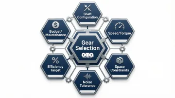
Factors to Consider
Shaft Configuration and Orientation
Shaft arrangement often narrows your options first. Determine if shafts are parallel (spur, helical, internal), intersecting (bevel), perpendicular non-intersecting (worm, hypoid), or if linear motion is needed (rack and pinion).
Speed and Torque Requirements
Start by calculating required gear ratio, operating speeds, and torque loads:
- High-speed applications favor helical or spiral bevel gears
- High-ratio needs (>10:1) may require worm or planetary gears
- Single-stage vs. multi-stage reduction depends on space and efficiency targets
Space and Weight Constraints
Physical limitations shape your gear selection significantly:
- Planetary gears deliver the highest power density
- Worm gears provide compact high-ratio solutions when space is tight
- Double helical gears need more axial space than single helical configurations
- Available mounting space and weight limits often eliminate certain options immediately
Physical and operational requirements work together. Once you've narrowed options by configuration and performance needs, environmental factors become critical.
Noise and Vibration Tolerance
- Helical, double helical, and spiral bevel gears operate quietly even at high speeds
- Spur and straight bevel gears generate more noise as speed increases
- Assess acceptable noise levels for your operating environment
- Weigh noise reduction benefits against additional manufacturing costs
Efficiency and Heat Generation
Energy consumption and thermal management impact long-term operating costs:
- Spur and helical gears deliver 94-99% efficiency
- Worm gears range from 50-90% efficiency and generate significant heat
- Calculate heat dissipation requirements for continuous operation
- Factor in cooling system costs and energy expenses over equipment lifetime
Environmental Conditions and Duty Cycle
- Operating environment affects material selection, lubrication needs, and gear durability
- Temperature extremes, contamination, and moisture exposure narrow material options
- Duty cycle matters: continuous operation, intermittent use, or shock loading each demand different designs
- Harsh conditions may require sealed housings and specialized alloys
Budget and Maintenance Considerations
Balance initial investment against total lifecycle costs:
- Spur gears offer the lowest initial cost but may not suit all applications
- Complex types like planetary or double helical gears cost more upfront but deliver better long-term value through efficiency and durability
- Evaluate maintenance accessibility and replacement part availability
- Factor in downtime costs when assessing gear reliability—custom-manufactured gears designed for your specific application often reduce failures and extend service intervals
What to Check Before Finalizing a Type of Industrial Gear
Verify Load Calculations: Confirm that calculated gear specifications (module/pitch, face width, material, heat treatment) meet or exceed the application's load and stress requirements. Use appropriate standards—AGMA 2101-D04 for design calculations or ISO 6336 for verification—rather than relying solely on manufacturer claims.
Note that ISO 6336 typically rates through-hardened gearing 5% to 35% lower than AGMA 2101, while carburized ratings are within 10%.
Confirm Bearing Selections: Ensure that bearing selections can handle both radial loads and any axial thrust generated by the gear type. Critical considerations include:
- Helical gears, spiral bevel gears, and hypoid gears generate significant axial forces
- Inadequate thrust bearing capacity causes premature failure
- Radial and axial load calculations must account for dynamic operating conditions
Validate Lubrication System: Verify that lubrication system design matches the specific gear type's requirements:
- Type, viscosity, delivery method, and cooling capacity must align with operating conditions
- Worm gears and hypoid gears require specialized lubricants with extreme pressure additives
- Worm gears often need AGMA Class 7/8 compounded oils or PAG synthetics for boundary lubrication
Conclusion
Industrial gears are precision mechanical components where type selection directly impacts equipment performance, reliability, and operating costs across demanding applications. With unplanned downtime costing major manufacturers up to $59 million annually per plant, proper gear selection is a critical engineering decision, not just a procurement task.
The nine main gear types each serve distinct purposes:
- Spur, helical, and double helical gears
- Bevel, worm, and hypoid gears
- Rack and pinion, internal, and planetary gears
Understanding their unique characteristics enables engineers to specify the optimal solution for their shaft configuration, load profile, and operational requirements, ensuring reliable performance and minimizing total cost of ownership.
For over 50 years, Carnes-Miller Gear has manufactured precision gears for aerospace, defense, medical, and industrial applications. With in-house capabilities for gear grinding (up to 400mm), cutting teeth (up to 200mm pitch diameter), and comprehensive custom manufacturing services, we help engineers select and manufacture the right gear type for demanding applications. Contact our technical team at 704-888-4448 or dan@cmgear.us to discuss your particular gear requirements.
Frequently Asked Questions
What are industrial gears?
Industrial gears are precision-engineered rotating components with teeth that mesh to transmit power, change speed ratios, or alter motion direction in heavy-duty machinery. They're designed to withstand continuous operation, heavy loads, and harsh environments.
What are the main types of industrial gears?
The nine primary types are spur, helical, double helical (herringbone), bevel, worm, rack and pinion, internal, planetary (epicyclic), and hypoid gears. Each is designed for specific shaft configurations and performance requirements.
Which is better for industrial applications: worm gear or helical gear?
Selection depends on your application. Worm gears excel in high-ratio (10:1 to 500:1), compact, self-locking applications but have lower efficiency (50-90%). Helical gears offer higher efficiency (98%+), greater load capacity, and speed capability for parallel shafts.
What factors determine gear life in industrial applications?
Gear life depends on proper type selection, adequate lubrication, correct loading, proper alignment, material quality with appropriate heat treatment, and operating environment factors like temperature, contamination, and duty cycle.
How do you calculate the required gear ratio for an application?
Gear ratio equals output speed divided by input speed (or input teeth divided by output teeth). The required ratio is determined by matching your motor or engine speed to the desired output speed of the driven equipment. For example, if your motor runs at 1,800 RPM and you need 180 RPM output, you need a 10:1 reduction ratio.
Can different gear types be mixed in the same gearbox?
Yes, it's common in multi-stage gearboxes like automotive transmissions and complex industrial drives. Each mesh must have compatible tooth forms, and the system must account for cumulative efficiency losses, thrust loads, and mounting requirements. Professional engineering analysis is essential for these custom designs.