Introduction
Internal gear cutting is a specialized manufacturing process essential for planetary gear systems, ring gears, and high-torque transmission applications across automotive, aerospace, and industrial sectors. Unlike external gear machining, manufacturers struggle with restricted tool access, interference risks, and specialized equipment requirements that directly impact precision and production efficiency.
The difference between success and scrap comes down to selecting the right method. Gear shaping, broaching, and power skiving each excel in different scenarios based on production volume, gear specifications, and proximity to shoulders.
This article explains the primary internal gear cutting methods, when each technique is appropriate, the step-by-step process, critical parameters, and common mistakes to avoid for achieving precision results.
Key Takeaways
- Specialized techniques—gear shaping, broaching, power skiving—machine internal gear teeth with precision
- Choose methods based on volume, AGMA precision requirements, and proximity to shoulders
- Master tool geometry, interference prevention, and runout minimization for consistent quality
- Avoid failures: calculate clearances accurately and account for heat treatment distortion
Primary Internal Gear Cutting Methods
Mastering internal gear cutting starts with understanding which method matches your production needs. The right choice balances volume requirements, precision standards, and geometric constraints—each method excels in specific scenarios.
Gear Shaping for Internal Gears
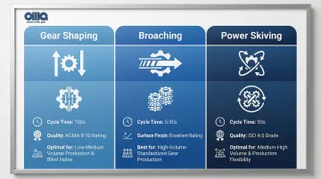
Gear shaping employs a reciprocating pinion-shaped cutter that creates teeth through synchronized vertical strokes and rotary indexing. This method is ideal for internal gears with obstructions or shoulders.
Performance Specifications:
- Precision: Achieves AGMA quality classes 8-10 (DIN 7-9 equivalent)
- Production rates: Approximately 180 seconds for a module 2, 57-tooth internal gear
- Module ranges: Suitable for wide range of sizes depending on machine stroke capacity
Advantages:
- Can cut close to shoulders and blind holes
- Handles interrupted tooth forms effectively
- Flexible for design changes without new tooling
Disadvantages:
- Slower cycle times due to non-cutting return stroke
- Limited by machine stroke length
- Lower productivity compared to continuous processes
Broaching for Internal Gears
For high-volume production runs, broaching delivers unmatched speed. This method pulls or pushes a long multi-tooth cutting tool through the workpiece in a single stroke, cutting all teeth simultaneously.
Performance Specifications:
- Cycle times: Extremely fast at 5-30 seconds per part, often under 20 seconds
- Surface finish: Excellent at Ra 0.4-0.8 µm
- Economic threshold: Cost-effective at volumes over 5,000-10,000 pieces
Advantages:
- Fastest cycle times available
- Excellent repeatability and surface finish
- Minimal operator intervention once set up
Disadvantages:
- High tooling investment ($8,000-$20,000 per broach)
- Dedicated tooling required for each gear design
- Cannot machine close to shoulders or blind holes
- Design changes require entirely new tools
While broaching excels at speed, it sacrifices flexibility. Power skiving bridges this gap with both speed and adaptability.
Power Skiving for Internal Gears
Power skiving employs a rotating gear-shaped cutter at a crossed-axis angle with synchronized spindles to create teeth continuously. This technology has become the dominant modern method for medium to high-volume production.
Performance Specifications:
- Productivity: 3-5 times faster than shaping (approximately 90 seconds for the same gear requiring 180 seconds to shape)
- Market growth: Internal gear skiving machine market valued at $156.7 million in 2024, projected to reach $316.8 million by 2033 (8.5% CAGR)
- Tool life: Carbide skiving tools can exceed HSS shaping tools by a factor of 6
- Precision: Achieves ISO quality grades 4-5
Advantages:
- 5-10 times faster than shaping for most applications
- Can machine close to shoulders (unlike broaching)
- Flexible CNC programming allows design changes
- Longer tool life with carbide cutters and advanced coatings
Disadvantages:
- Requires sophisticated CNC machines with synchronized spindles
- Complex setup calculations for crossed-axis angles
- Higher initial equipment investment
- Demands precise spindle synchronization (even 1 RPM mismatch causes vibration)
Comparison Table: When to Use Each Method
| Feature | Gear Shaping | Broaching | Power Skiving |
|---|---|---|---|
| Production Volume | Low to Medium | High to Very High | Medium to High |
| Cycle Time | Slow (180s typical) | Very Fast (5-30s) | Fast (90s typical) |
| Proximity to Shoulders | Excellent | Poor (requires clearance) | Good |
| Flexibility | High | Low (dedicated tooling) | High (programmable) |
| Initial Investment | Low to Moderate | High ($8k-$20k per tool) | High (CNC equipment) |
| Typical Applications | Prototypes, blind holes, low volume | Mass production, standardized gears | Medium-high volume, complex geometries |
Step-by-Step Internal Gear Cutting Process
Step 1: Design Validation and Interference Checking
Verify your internal gear design avoids interference issues before you start cutting. Internal gears face three common interference types that can compromise performance:
Interference Types to Check:
- Involute interference: Pinion tip digging into gear root
- Trochoid interference: Problems at tooth contact exit
- Trimming interference: Radial assembly impossible due to geometric constraints
Calculate minimum and maximum allowable mating pinion teeth using formulas based on internal gear tooth count and pressure angle. Reference AGMA 908-B89 for geometry factors and AGMA 911-B21 (Annex A) for internal gear geometry guidelines.
Use gear design software like KISSsoft to validate designs according to ISO 1328 and DIN standards, checking for collisions and interference before manufacturing begins.
Step 2: Workpiece Preparation and Fixturing
Your blank preparation directly impacts final gear quality. Precision at this stage determines whether you'll achieve the required tolerances in finished parts. Start with proper blank machining and verify material properties before cutting.
Blank Preparation Requirements:
- Machine bore diameter, face width, and datum features to precise specifications
- Ensure total runout control (specific tolerances depend on application requirements)
- Verify material hardness is appropriate for cutting operations
- Provide adequate stock allowance per flank for finishing operations
Workholding Selection: Select appropriate fixturing (mandrel, chuck, or fixture plate) that provides:
- Rigid support without distortion
- Tool access to internal diameter
- Stability for thin-walled components to prevent deflection during cutting
Step 3: Tool Selection and Setup
Your tool selection and setup directly affect cutting performance, tool life, and final gear quality. Match the cutter specifications precisely to your gear requirements.
Cutter Selection Criteria:
- Module or diametral pitch matching gear specification
- Pressure angle (typically 20°)
- Helix angle for helical internal gears
- Number of teeth appropriate for the application
- Required profile modifications (tip relief, protuberance)
Power Skiving Setup: Calculate proper crossed-axis angle (typically 15-35°, with 20° often optimal for internal gears) balancing cutting speed against collision avoidance. Ensure tool diameter provides adequate rigidity while fitting within the internal gear geometry.
Tool Mounting: Mount tool with minimal runout (<0.01mm where possible), verify cutting edge condition, and set proper rake and clearance angles specific to workpiece material.
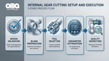
Step 4: Parameter Optimization and Cutting
Cutting parameters must balance productivity, tool life, and surface finish requirements. Use this reference table for typical parameter ranges:
| Parameter | HSS Tools | Carbide Skiving |
|---|---|---|
| Cutting Speed | 50-90 m/min | 150-250 m/min (up to 300+ m/min) |
| Roughing Depth | 0.5-2mm | 0.5-2mm |
| Semi-Finishing Depth | 0.2-0.5mm | 0.2-0.5mm |
| Finishing Depth | 0.05-0.15mm | 0.05-0.15mm |
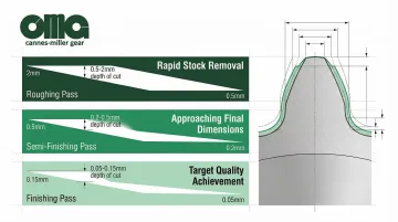
Program your operations in stages. Start with roughing passes for rapid material removal, move to semi-finishing for approaching final dimensions, and complete with finishing passes for final accuracy and surface finish.
Process Monitoring: Monitor cutting forces, vibration, and chip formation during initial cuts. Adjust parameters if you observe excessive tool wear, poor surface finish, or chatter.
Step 5: In-Process Inspection and Final Verification
Quality control throughout the process prevents costly rework. Catching issues early ensures you meet specifications without expensive corrections.
In-Process Checks: Measure tooth profile, lead, and pitch using gear inspection equipment or CMM after roughing to verify the process is within tolerance before finishing operations.
Final Inspection: Conduct complete measurement of:
- Tooth thickness
- Profile accuracy
- Lead accuracy
- Pitch variation
Verify against specification standards such as ISO 1328-1 (11 tolerance classes) or DIN 3962 quality grades.
Quality Control Frequency: Implement statistical process control with regular sampling based on production volume and criticality of application.
When and Why to Use Internal Gear Cutting
Internal gear cutting is not always the best manufacturing approach—the decision depends on application requirements, production volume, and design constraints.
Typical Applications Where Internal Gear Cutting is Essential
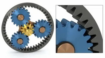
Internal gears serve as ring gears in planetary arrangements, the most common application for internal gear cutting. These systems are used extensively in automotive transmissions (automatic and EV), industrial gearboxes, and aerospace actuators.
Planetary gear systems account for 39% of the automotive gear reducer market, driven by demand for compact, high-torque solutions in electric vehicles. Internal gears represent 17% of the automotive gear market overall.
Beyond planetary systems, internal gears appear in numerous critical applications:
- Rotary actuators requiring compact design
- Gear pumps for hydraulic systems
- Differential assemblies in automotive drivetrains
- High-torque transmission systems where space is limited
Industry analysts project the global precision gearbox market will reach $10.69 billion by 2035, largely driven by EV adoption.
When External Gears May Be a Better Choice
When design allows, external gear configurations may offer simpler manufacturing, lower tooling costs, and easier inspection. For low-volume applications where tooling investment cannot be justified, consider redesigning to use external gears.
Certain size ranges also present challenges for internal gear cutting:
- Very large internal gears (>500mm diameter) may have limited tooling availability
- Very small modules (<0.5mm) require specialized equipment
- Power skiving becomes difficult if spline depth exceeds internal diameter
- Broaching is generally limited to gears smaller than 200mm due to force and tool size constraints
Prerequisites and Setup Requirements
Proper preparation and equipment capabilities directly impact achievable precision, tool life, and production efficiency.
Machine and Tooling Requirements
Minimum Machine Specifications:
- Adequate spindle power (5-30 kW depending on gear size)
- Rigid construction to minimize deflection
- Synchronized spindle control for skiving operations
- Programmable axis control for complex tooth forms
- Precise RPM ratio maintenance (critical for skiving—even 1 RPM mismatch causes problems)
Required Tooling:
- Precision broaches, shaper cutters, or skiving tools matched to module and pressure angle specifications
- Tool holders with minimal runout (<0.0002" TIR)
- Workholding fixtures designed for internal gear geometry
- Adequate tool clearance for access to internal diameter
Material and Workpiece Readiness
Material Condition:
- Hardness verified within specified range (typically 180-240 BHN for pre-hardened steels)
- Stress-relieved to prevent distortion during or after cutting
- Uniform grain structure confirmed through material certification
- Heat treatment compatibility verified for post-cut operations
Blank Preparation:
- Machine bores to ±0.002" tolerance or better
- Maintain 0.015-0.030" stock allowance per side for finishing operations
- Establish datum surfaces perpendicular within 0.001" for inspection reference
- Verify material properties (hardness, composition, heat treat condition) before cutting begins
Key Parameters That Affect Results
Internal gear cutting outcomes—precision, surface finish, tool life, and cycle time—depend heavily on controlling several interrelated parameters.
Cutting Speed and Feed Rate
Cutting speed must balance material removal rate with tool material capabilities and workpiece hardness.
Optimal Speed Ranges by Material:
- Steel (general): 150-200 m/min for carbide skiving
- Lower strength materials: Can use higher speeds (up to 250 m/min)
- HSS shaping: 50-90 m/min typical
Tool Life Trade-offs: Speed selection directly impacts how long your tools last. Reducing cutting speed by 50% in HSS shaping can increase tool life by a factor of 3-5. Surprisingly, for lower strength materials (Rm = 1,200 MPa), increasing cutting speed in dry skiving from 120 to 140 m/min can actually increase tool life due to thermal softening of the workpiece.
Crossed-Axis Angle (for Power Skiving)
The angle between tool and workpiece axes critically affects chip formation, cutting forces, and tool life.
Optimal Angle Selection:
- Typical range: 15-35° for internal gears
- Optimal compromise: 20° balances cutting speed and collision avoidance
- Larger angles: Increase productivity but may reduce precision
- Smaller angles: Better for precision but slower cutting speeds
Calculation Factors: Optimal angle depends on:
- Helix angle of the gear
- Module size
- Whether machining spur or helical internal gears
- Tool shaft clearance requirements
Depth of Cut and Number of Passes
Balancing aggressive material removal against conservative cuts affects cycle time, tool wear, and surface finish.
Recommended Depth Guidelines:
| Pass Type | Depth of Cut | Purpose |
|---|---|---|
| Roughing | 0.5-2mm | Rapid stock removal |
| Semi-finishing | 0.2-0.5mm | Approaching final dimensions |
| Finishing | 0.05-0.15mm | Achieving target quality grades |
Multi-Pass Strategy: Use logarithmic decrease in depth of cut to maintain surface quality while maximizing productivity.
Tool Geometry and Coating Selection
Tool design and coatings significantly impact performance in the confined space of internal gear cutting.
Rake and Clearance Angles: Skiving tools often use negative rake angles (up to -50° effective rake during cutting), increasing tool load but necessary for the cutting kinematics.
Clearance angles must be optimized for chip evacuation in the confined space.
Advanced Coatings: AlCrN (Aluminum Chromium Nitride) coatings prove superior to traditional TiAlN for skiving applications, offering:
- Better adhesion and thermal stability
- Significantly extended tool life
- Improved performance in both wet and dry cutting
Dry vs. Wet Cutting: Dry skiving strategies can increase tool life by 1.5 to 3 times for lower-strength materials compared to wet machining, due to thermal effects that soften the workpiece material during cutting.
Workpiece Clamping and Rigidity
Inadequate clamping or thin-walled ring gears can deflect during cutting. This deflection causes tooth spacing errors, profile inaccuracies, and chatter.
Clamping Requirements:
- Calculate required clamping force based on cutting forces
- Design support fixtures for thin-walled internal gears
- Maintain dimensional stability throughout cutting
- Prevent distortion that would cause tolerance failures
Common Mistakes and Troubleshooting
Skipping Interference Calculations Before Cutting
Cutting an internal gear that cannot properly mesh with its pinion creates costly rework. Involute, trochoid, or trimming interference can prevent proper meshing even when individual tooth profiles appear correct.
Interference checks are critical for roughing and semi-finishing passes, not just the final form.
Solution: Always calculate allowable pinion tooth range and verify design before manufacturing. Use gear design software to validate geometry according to AGMA or DIN standards.
Inadequate Tool Clearance Planning
Tool collision with shoulders, bores, or other features during cutting can damage both workpiece and tooling. In internal skiving, the tool shaft must clear the face of the internal gear throughout the entire cutting cycle.
Solution:
- Verify clearances in CAM simulation before cutting
- Ensure adequate relief features in gear design
- Select appropriate tool diameter and length for access
- Consider crossed-axis angle effects on tool holder clearance
Poor Surface Finish or Chatter Marks
Chatter marks and poor surface finish typically stem from tool overhang creating vibration, incorrect cutting parameters, or dull cutting edges. Workpiece clamping issues and spindle synchronization problems (particularly in skiving) also contribute to surface defects.
Corrective Actions:
- Reduce tool overhang and optimize cutting speed/feed for your material
- Inspect and replace worn tools regularly
- Verify machine rigidity and improve workholding to prevent deflection
- Check spindle synchronization—critical for skiving operations
- Review machine condition and calibration if issues persist
Target Surface Finish:
- Power skiving: Ra 0.4-0.6 µm achievable
- Broaching: Ra 0.4-0.8 µm typical
- After grinding: Ra 0.4-0.8 µm for precision applications
Tooth Spacing or Profile Errors
Likely Causes:
- Excessive runout in tool or workpiece mounting
- Backlash in machine axes
- Thermal growth during cutting
- Incorrect tool geometry or indexing errors
- Thin-walled part deflection
Solution:
- Measure and minimize runout to <0.01mm target
- Compensate for machine backlash and allow thermal stabilization before precision operations
- Verify tool dimensions match specifications and calibrate indexing accuracy
- Use proper fixturing for thin-walled components to prevent deflection
Experienced manufacturers like Carnes-Miller Gear use in-house inspection capabilities—including nital-etch testing for grinding burns—to catch and correct these issues before final delivery, ensuring gears meet AGMA quality standards.
Conclusion
Mastering internal gear cutting requires selecting the right method: shaping for flexibility and blind holes, broaching for ultra-high volume standardized production, or power skiving for the best balance of speed and versatility.
Success depends on thorough preparation. This includes interference validation, precise workpiece setup, optimized parameters, and rigorous quality control throughout the process.
Internal gear cutting presents unique challenges compared to external gears, particularly tool access, interference risks, and specialized equipment requirements. However, modern CNC technology and advanced tooling have made high-precision, efficient production achievable across a wide range of applications.
The rapid adoption of power skiving demonstrates how innovation continues to improve productivity. With the market growing at 8.5% annually, manufacturers can now maintain the precision demanded by automotive, aerospace, and industrial applications while increasing throughput.
For custom internal gear manufacturing requirements, job shops like Carnes-Miller Gear (with over 50 years of expertise) can provide consultation on method selection, feasibility analysis, and turn-key production services tailored to your specific application.
Frequently Asked Questions
What are the different methods of internal gear cutting?
The three primary methods are gear shaping (reciprocating cutter), broaching (single-stroke multi-tooth tool), and power skiving (continuous rotary cutting). Shaping suits low-volume and restricted geometries, broaching handles high-volume standardized runs, and power skiving balances speed with design flexibility.
What is the fastest method of internal gear cutting?
Broaching offers the fastest cycle time (5-30 seconds per part) for high-volume production but requires dedicated tooling for each design. Power skiving runs 3-5 times faster than shaping while maintaining design flexibility.
How do you determine the gear cutter size for internal gear cutting?
Calculate cutter size based on the internal gear's root diameter, tooth count, and required clearances—balancing interference avoidance with tool rigidity. Power skiving requires additional consideration of crossed-axis angle and shaft clearance constraints.
What tolerances can be achieved with internal gear cutting?
Shaping and power skiving typically achieve AGMA Quality Class 8-10 (DIN 7-9 or ISO 4-5), while broaching delivers Ra 0.4-0.8 µm surface finishes. Grinding after heat treatment reaches AGMA 12-13 for precision applications.
Can internal gears be cut after heat treatment?
Yes, though most cutting occurs before heat treatment. Hard cutting and grinding can be performed after hardening (45-62 HRC) to correct distortion and achieve final precision, using specialized tooling for hardened materials.
What are common defects in internal gear cutting and how to prevent them?
Common defects include tooth spacing errors (runout/indexing), profile inaccuracies (tool wear/deflection), surface finish issues (chatter/parameters), and interference problems (design errors). Prevent through proper setup with minimal runout, optimized parameters, in-process inspection, and thorough pre-manufacturing interference checking.