Introduction
When manufacturers need internal helical gears or components with geometric constraints, gear shaping remains the most reliable cutting method—a position it's held for over 50 years. These gears deliver smoother operation, higher load capacity, and significantly reduced noise compared to spur gears.
The process appears straightforward: a reciprocating cutter synchronized with helical motion. Yet achieving precise helix angles and accurate tooth profiles demands rigorous understanding of machine setup, cutter selection, and process parameters.
Small deviations in helical guide calibration or feed rates cascade into costly quality issues. Gear mesh performance suffers, service life shortens, and rework becomes necessary. This guide explores the critical methods for mastering helical gear shaping—from setup fundamentals to troubleshooting common defects.
Key Takeaways
- Uses reciprocating cutters with helical motion to create precise teeth on internal/external gears
- Ideal for internal gears, shoulder-adjacent gears, and production runs under 500 pieces
- Critical factors: helical guide setup, cutter selection, machine calibration, and cutting parameters
- Achieve quality results through helix angle precision, optimized feed rates, and effective coolant use
How to Shape Helical Gears: Step-by-Step Process
Step 1: Machine and Workpiece Setup
Proper workpiece mounting is the foundation of quality helical gear shaping. Runout in the fixture creates pitch and profile errors.
Workpiece mounting requirements:
- Concentricity verification: Measure total indicated runout (TIR) on the mounting surface. Excessive runout causes cutting force variation and deflection
- Fixturing rigidity: Use hydraulic or mechanical clamping to prevent workpiece deflection under reciprocating cutting forces
- Alignment verification: Ensure the workpiece axis is perpendicular to the cutter stroke direction
Helical guide installation: Modern CNC shapers with electronic helical guides (like the Liebherr LS-E series) eliminate mechanical guide fabrication, reducing setup times from hours to minutes.
Electronic systems allow instant helix angle corrections via CNC controller without physical changeovers. For mechanical guides, install the guide matching the required helix hand (LH/RH) and calculated lead, then confirm proper engagement before cutting.
Cutter arbor setup:
- Measure arbor runout using a dial indicator—excessive runout creates tooth form errors
- Apply proper clamping torque per machine specifications to prevent cutter slippage
- Ensure cutter mounting interface (taper shank, flat-back disc) is clean and undamaged
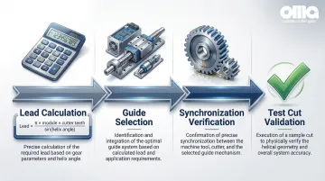
Step 2: Helical Guide Configuration
Once the workpiece and cutter are mounted, configure the helical guide to match the cutter's helix geometry.
The guide lead must match the axial pitch of the cutter's helix. Incorrect lead settings create cumulative pitch deviations and helix angle errors.
Lead calculation formula:
Lead = (π × module × cutter teeth) / sin(helix angle)
Where:
- Module = normal module (mn)
- Cutter teeth = number of teeth on the shaper cutter
- Helix angle = required helix angle (β)
Verification methods:
- For electronic guides, input the calculated lead into the CNC controller and verify synchronization through test cuts
- For mechanical guides, confirm the guide lead matches the calculation. Shared guides for different cutters must have lead angle error (fHβ) within acceptable tolerances (typically < 3 µm for quality grades)
- Ensure that guide hand (LH/RH) matches gear requirements—incorrect hand produces the opposite helix direction
Step 3: Cutter Positioning and Initial Passes
With the helical guide configured, position the cutter and begin material removal.
Radial positioning: Calculate the center distance between cutter and workpiece based on gear blank diameter, cutter diameter, and required depth of cut. Incorrect radial positioning causes tooth thickness errors.
Roughing pass parameters:
- Depth of cut: Maximize material removal while staying within machine power limits
- Stroke rate: Modern machines achieve up to 1,500 double strokes per minute
- Feed per stroke: Typical radial feed rates range from 0.10 to 0.40 mm/tooth depending on material hardness
Initial cut monitoring:
- Inspect proper tooth form development after the first few teeth
- Monitor for excessive tool deflection or vibration
- Adjust feed rates if surface quality issues appear
Step 4: Finishing Passes and Quality Verification
After roughing removes the bulk of material, finishing passes achieve final dimensional accuracy and surface finish.
Finishing pass parameters:
- Reduce feed rates by 30-50% compared to roughing to achieve required surface finish
- Optimize stroke speed for surface quality—too fast creates chatter, too slow reduces productivity
- Maintain consistent coolant flow to manage heat and chip evacuation
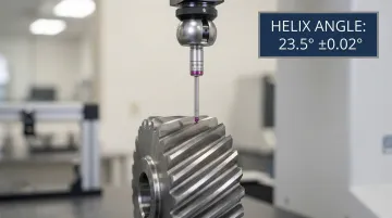
In-process checks:
- Helix angle accuracy: Per ISO 1328-1, measure helix slope deviation (fHβ) over the helix evaluation range using the least squares method
- Tooth thickness: Measure with span measurement or over-pins measurement
- Surface finish: Inspect for tool marks, chatter, or excessive roughness
Post-shaping inspection: Use precision measuring centers like the Klingelnberg P 40 to inspect profile, lead (helix), and pitch errors in a fully automatic cycle.
Modern shapers typically achieve AGMA 10-12 quality in the green (pre-heat treat) condition.
When Should You Use Helical Gear Shaping?
Helical gear shaping works best for specific applications but is not always the most economical choice. Understanding when to shape versus hob or mill determines project success.
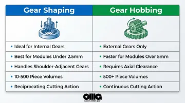
Shaping becomes the preferred method in these scenarios:
- Internal helical gears where hobbing cannot access internal tooth forms
- Gears positioned close to shoulders or flanges where hob diameter causes interference
- Cluster gears with multiple gears on one shaft where one obstructs the cutter path
- Production volumes of 10-500 pieces requiring flexibility and reasonable economics
Shaping loses its advantage in these situations:
- High-volume production exceeding 500 pieces/year—hobbing reduces unit costs by over 30%
- Large module gears above 5mm where hobbing is 2-3x faster
- Hardened gears requiring AGMA 12+ quality where grinding achieves superior finish
- External gears with tight cycle times where hobbing's continuous action is faster
The shaping sweet spot: For gears with modules < 2.5 mm, shaping is more efficient and accurate than hobbing. Between 2.5-5 mm, productivity is roughly equal.
What You Need Before Shaping Helical Gears
Proper preparation and equipment readiness directly determine whether quality targets will be met.
Equipment and Tooling Requirements
Essential equipment:
- Gear shaping machine with helical guide capability—modern machines with electronic guides (Liebherr LS-E series, Gleason GP series with ES option) offer maximum flexibility
- Properly sharpened helical shaper cutter matching gear specifications including pressure angle, module, and helix angle
- Precision measuring instruments for helix angle verification, tooth geometry inspection, and lead deviation measurement
The shaper cutter itself requires careful selection based on your application.
Cutter specifications:
- PM-HSS (Powder Metallurgy High-Speed Steel) for general applications; carbide for high-volume production and harder materials
- Cutter helix angle must match the guide lead calculation
- Available in disk, deep counterbore, and shank types depending on workpiece geometry
Workpiece and Material Considerations
The gear blank must meet specific requirements before shaping begins.
Gear blank requirements:
- Bore and mounting surfaces finished to minimize runout
- Material hardness typically 180-250 HB for green machining before heat treatment
- Stock allowance for finishing operations and heat treat distortion correction
Common materials include steel alloys (SCM 415, 4140), cast iron, and bronze. Material hardness directly affects feed rate selection and tool life.
Operational Readiness
Operator requirements:
- Understanding of gear terminology and helical geometry
- Ability to interpret technical drawings and tolerance specifications
- Experience with CNC machine operation and setup procedures
Proper support systems ensure consistent results and safe operation.
Support systems:
- Oil-based coolants for tougher materials; synthetic coolants for improved cooling and chip evacuation
- Coolant delivery with adequate flow rate and proper direction to manage heat and remove chips
- Safety procedures for cutter operations, including proper guarding and emergency stops
Key Parameters That Affect Results in Helical Gear Shaping
Helical gear quality depends on precise control of machine settings and cutting variables.
Helix Angle and Lead Accuracy
Helix angle deviation (fHβ) directly impacts gear mesh quality and load distribution.
Gears with excessive helix errors experience uneven loading, increased noise, and premature wear.
Tolerance standards: ISO 1328-1 and AGMA 2015 define acceptable helix angle deviations based on gear quality grade. For example:
- AGMA 10 (ISO 6): Moderate precision for general industrial applications
- AGMA 12 (ISO 4): High precision for automotive and aerospace
- AGMA 13+ (ISO 3 and better): Ultra-precision requiring grinding
Modern systems with electronic helical guides allow micron-precise corrections to meet these grades. This eliminates the need for regrinding tools or changing mechanical guides.
Cutter Selection and Geometry
Cutter pressure angle, number of teeth, and rake angle influence cutting forces and surface finish.
Key considerations:
- Pressure angle: Must match gear specification (typically 20° or 25°)
- Number of cutter teeth: Affects the lead calculation and cutting smoothness
- Rake angle: Varies along the cutting edge, affecting chip formation and cutting forces
For steel workpieces (180-250 HB), PM-HSS cutters are standard. For higher hardness or production volumes, carbide offers better wear resistance.
Once you've selected the right cutter, operational parameters determine how effectively it performs.
Feed Rate and Cutting Speed
The relationship between feed per stroke, stroke rate, and resulting surface roughness determines both quality and productivity.
Typical feed rate ranges:
- Steel: 0.10-0.25 mm/tooth for roughing; 0.05-0.15 mm/tooth for finishing
- Cast iron: 0.15-0.30 mm/tooth for roughing; 0.08-0.20 mm/tooth for finishing
- Bronze: 0.20-0.40 mm/tooth for roughing; 0.10-0.25 mm/tooth for finishing
Finding the right balance requires weighing multiple factors:
- Higher feed rates boost productivity but compromise surface finish
- Aggressive feeds accelerate tool wear and replacement costs
- Quality requirements may dictate conservative feeds despite longer cycle times
- Tool life economics often favor moderate feeds over maximum speed
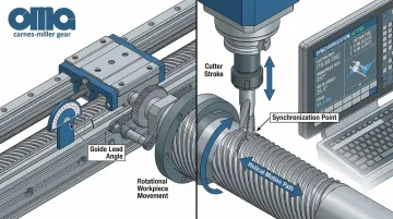
Helical Guide Synchronization
Guide lead errors create cumulative pitch deviations and apex point inaccuracies on the finished gear.
Calculate the required lead using the formula: Lead = (π × module × cutter teeth) / sin(helix angle). Then verify accuracy based on your guide type:
- Mechanical guides: Verify physical guide lead matches calculation within tolerance
- Electronic guides: Confirm CNC synchronization through test cuts and measurement
Shared guides for different cutters require special attention.
Calculate and verify lead angle error (fHβ) to ensure it falls within acceptable limits (< 3 µm for precision grades).
Coolant Application and Chip Evacuation
Coolant flow rate and direction affect tool temperature, chip formation, and surface quality.
Effective coolant application requires attention to several factors:
- Oil-based coolants: Better lubrication for tougher materials and slower cutting speeds
- Synthetic coolants: Improved cooling capacity and chip evacuation for higher speeds
- Flow rate: Adequate volume to flood the cutting zone and remove chips continuously
- Direction: Aim coolant at the point of cut, not just the general cutter area
Dry machining considerations: While hobbing and skiving increasingly use dry cutting with carbide tools, shaping typically relies on coolant/oil for heat management and chip control.
Common Mistakes When Shaping Helical Gears
Improper Helical Guide Calibration
Incorrect helical guide lead settings produce gears with wrong helix angles, causing mesh problems, increased noise, and premature wear.
Even small deviations accumulate across the tooth face width, creating significant errors. Verification before cutting prevents costly errors:
- Confirm lead calculations match gear specifications
- For electronic guides: input correct parameters and run test cuts
- For mechanical guides: physically measure guide lead against calculated requirements
- Document settings for repeatability across production runs
Excessive Feed Rates
Aggressive feed rates cause poor surface finish, increased tool wear, and potential tooth form errors. Higher feeds may improve productivity, but they compromise quality and tool life.
Finding the optimal feed rate requires a systematic approach:
- Start with conservative feeds based on material hardness and cutter specs
- Gradually increase while monitoring surface finish and tool condition
- Never exceed manufacturer recommendations for cutter material and geometry
- Document successful parameters for similar materials
Inadequate Workpiece Rigidity or Fixturing
Insufficient clamping or poor fixture design allows workpiece deflection during cutting, creating lead variations and runout errors. The reciprocating cutting force in shaping is significant and requires robust workholding.
Proper fixturing eliminates deflection-related errors:
- Use hydraulic or mechanical clamping with adequate force
- Verify workpiece concentricity before cutting begins
- Design fixtures to minimize overhang and maximize rigidity
- Inspect fixtures regularly for wear that could compromise accuracy
Troubleshooting Issues in Helical Gear Shaping
Even with proper setup, production issues can emerge during helical gear shaping. The following troubleshooting guide addresses three common problems and their solutions, helping you maintain consistent quality across production runs.
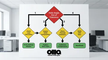
Problem: Helix Angle Deviation Outside Tolerance
Helix angle deviation typically stems from four root causes: incorrect helical guide lead settings (the most common issue), worn mechanical guide components, thermal expansion during extended runs, or CNC synchronization errors in electronic systems.
Corrective actions:
- Verify lead calculations against machine settings
- Inspect and replace worn mechanical guide components
- Implement thermal compensation in the CNC controller
- Adjust cycle times to allow cooling between operations
- Recalibrate axis synchronization for electronic guides
Problem: Poor Surface Finish or Tool Marks
| Cause | Diagnostic Check | Solution |
|---|---|---|
| Dull or damaged cutter | Visual inspection for wear, chipping | Resharpen or replace cutter |
| Improper feed rate | Monitor for inconsistent cutting speed | Reduce feed rate; optimize stroke speed |
| Inadequate coolant | Check flow rate and coolant type | Increase flow or switch coolant formulation |
| Machine vibration | Inspect mounting and structural rigidity | Tighten components; address foundation issues |
Problem: Inconsistent Tooth Thickness or Profile Errors
Tooth thickness and profile inconsistencies often indicate progressive cutter wear, incorrect radial positioning, material hardness variations, or thermal growth during extended runs.
To resolve these issues:
- Monitor cutter wear: Measure diameter periodically and adjust radial position to compensate
- Verify center distance: Confirm calculations match machine settings
- Test material hardness: Check incoming blanks and adjust parameters for harder or softer lots
- Control thermal effects: Let the cutter reach equilibrium before critical production
- Implement measurement cycles: Schedule periodic checks and adjustments during long runs
Alternatives to Helical Gear Shaping
Other methods may offer better economics, quality, or capability depending on application requirements.
Gear Hobbing
Hobbing uses a continuous generating process with a rotating hob cutter, making it faster and more economical for external helical gears in medium to high volumes.
Advantages:
- 2-3x faster cycle times for modules > 5 mm
- Lower unit costs for production volumes > 500 pieces (over 30% cost reduction)
- Continuous cutting action improves productivity
Trade-offs:
- Cannot cut internal gears (physical limitation)
- Needs axial tool overrun space (typically 2-3x the module)
- Less suitable for gears near shoulders or in cluster gear configurations
5-Axis Milling
Multi-axis CNC milling offers maximum flexibility for complex geometries, prototypes, and herringbone gears without dedicated tooling.
Advantages:
- No special cutters required—standard end mills
- Can produce any gear profile including complex geometries
- Ideal for prototypes and design iterations
Trade-offs:
- Significantly longer cycle times (often 10-20x slower than shaping)
- Higher equipment cost for 5-axis CNC machines
- Demands CAM programming expertise and software
- Not cost-effective for production volumes > 10-20 pieces
Gear Grinding (Hard Finishing)
Grinding achieves superior surface finish and accuracy for hardened gears in precision applications, typically after heat treatment.
Advantages:
- Can achieve AGMA 13+ quality (ISO 3 and better)
- Works on hardened gears (55-62 HRC)
- Superior surface finish eliminates need for further operations
Trade-offs:
- Works only on pre-cut gears as a finishing operation
- Slower process than cutting operations
- More expensive tooling costs for grinding wheels
- Typically reserved for applications requiring AGMA 12+ quality where shaping/hobbing alone is insufficient
Professional Gear Manufacturing Services
After evaluating manufacturing methods, many companies find that outsourcing to specialized gear shops makes sense for complex specifications, low volumes, or when in-house helical shaping capability is unavailable.
When to consider outsourcing:
- Complex specifications requiring AGMA 10-13 quality ratings
- Low production volumes (< 100 pieces) where setup time dominates
- Lack of in-house helical shaping equipment or expertise
- Need for certified quality standards with full inspection reports
- Requirements for integrated services (cutting, heat treatment, grinding, inspection)
Trade-offs:
- Longer lead times than in-house production (typically 4-8 weeks)
- Less control over production scheduling and priorities
- Higher piece-part cost compared to in-house at volume
Established gear manufacturers like Carnes-Miller Gear offer full-service capabilities including gear shaping, hobbing, and grinding (up to 400mm diameter), eliminating coordination between multiple vendors. With over 50 years of experience, they maintain AGMA 10 ratings on shaped gears and AGMA 13 on ground gears.
For companies without dedicated gear shaping equipment or requiring specialized expertise, partnering with an experienced manufacturer provides access to precision gear production without capital equipment investment.
Conclusion
Successful helical gear shaping requires precise helical guide setup, proper cutter selection, and disciplined control of cutting parameters. The difference between AGMA 10 and AGMA 8 quality—or between acceptable mesh performance and premature failure—often comes down to micron-level attention to helix angle accuracy and feed rate optimization.
Most quality issues stem from three sources:
- Inadequate machine calibration
- Improper feed rates
- Insufficient workpiece preparation
Electronic helical guides have revolutionized the process by eliminating mechanical guide changeovers and enabling instant corrections. However, fundamental principles remain unchanged: the lead calculation must be correct, the cutter must be sharp and properly mounted, and cutting parameters must match material properties.
Choosing the right method balances production volume, quality requirements, equipment availability, and economic considerations. Shaping dominates for internal gears and components with geometric constraints, while hobbing wins for high-volume external gears. For complex projects requiring precision helical gears, manufacturers like Carnes-Miller Gear deliver AGMA 10 shaping and AGMA 13 grinding capabilities backed by 50 years of production expertise—ensuring quality results without the capital investment in specialized equipment.
Frequently Asked Questions
What is the difference between shaping helical gears and spur gears?
Helical gear shaping requires a synchronized helical guide to generate the helix angle during cutter reciprocation, whereas spur gear shaping uses only vertical reciprocation. The helical guide rotates the workpiece in precise synchronization with the cutter stroke.
Can you shape internal helical gears?
Yes, gear shaping is the preferred method for internal helical gears since hobbing cannot physically access internal tooth forms. Shaping handles internal gears from 25-400mm diameter with modules from 0.5-12mm depending on machine capacity.
How do you calculate the correct helical guide lead?
Use the formula: Lead = (π × module × cutter teeth) / sin(helix angle). For example, a gear with 2mm module, 20-tooth cutter, and 30° helix angle requires: Lead = (3.14159 × 2 × 20) / sin(30°) = 251.3mm.
What causes helix angle errors in shaped gears?
Primary causes include incorrect guide lead setting, guide component wear, thermal expansion during production runs, workpiece deflection from inadequate clamping, and CNC synchronization errors. Mitigation strategies include verifying lead calculations, regular guide inspection, thermal compensation, and robust fixturing.
How does helical gear shaping compare to hobbing in terms of speed?
Hobbing is generally 3-5x faster for external gears due to continuous cutting action, but shaping remains necessary for internal gears and gears near shoulders. For modules under 2.5mm, shaping is actually more efficient than hobbing.
What AGMA quality grades can be achieved with gear shaping?
Modern gear shaping typically achieves AGMA 10-12 quality in the green (pre-heat treat) condition, with AGMA 13+ possible after hard finishing operations like grinding. Electronic helical guides enable micron-precise corrections for higher quality grades.