Introduction: Why Helical Gear Optimization Matters
Engineers selecting helical gears face a critical challenge: these components promise smooth, quiet operation and exceptional load capacity, but realizing those benefits depends entirely on precision design and manufacturing decisions. Wrong choices lead to premature failure, excessive noise, and unplanned downtime — consequences that ripple fast through production schedules in aerospace, defense, and industrial applications where replacement lead times are measured in weeks, not days.
Performance hinges on five interconnected variables: helix angle, tooth contact geometry, manufacturing process, heat treatment, and surface finish. Each decision cascades through the design, affecting everything from bearing loads to service life.
This guide covers how to engineer each variable precisely — and how to avoid the common pitfalls that compromise helical gear performance in demanding applications. It's written for mechanical engineers, OEM designers, and procurement specialists working in aerospace, defense, industrial, and transportation sectors.
TLDR: Key Takeaways
- Helix angles between 15°–45° balance axial stability and load sharing — speed, noise, and thrust requirements determine the right angle
- Helix angle modification compensates for torsional deflection, cutting peak stress by up to 28%
- Choose your manufacturing process based on required AGMA quality — hobbing reaches AGMA 10–11; grinding achieves AGMA 12–13
- Post-treatment grinding corrects heat treatment distortion and restores tight tolerances
- Specify AGMA quality grade upfront based on application criticality
Helix Angle Selection: The Starting Point for Performance
The helix angle—the angle between the gear tooth helix and the axis of rotation—is the single most influential design parameter in a helical gear. This angle controls contact ratio, axial thrust load, noise characteristics, and load distribution across the tooth face.
The Trade-Off Range
Smaller angles (15°–20°):
- Favor axial stability with lower thrust loads
- Suited for space-constrained applications
- Preferred when bearing capacity limits axial load
- Used where housing deflection is a concern
Larger angles (30°–45°):
- Produce smoother, quieter meshing
- Achieve higher contact ratios with more teeth sharing load
- Preferred in high-speed power transmission
- Standard in automotive and industrial drives where NVH reduction is the priority
Contact Ratio and Load Distribution
Increasing helix angle raises the overlap ratio (εβ), calculated as εβ = (b sin β) / (π mn), where b is face width and mn is normal module. More teeth share the transmitted load at once, reducing peak stress per tooth. According to Shigley's Mechanical Engineering Design, higher overlap ratios distribute load more evenly, reducing peak tooth stress and extending fatigue life.
Managing Axial Thrust
Larger helix angles generate higher axial thrust loads, calculated as Wa = Wt × tan β, where Wt is the tangential load. Designers must accommodate this thrust through appropriately rated bearings and adequately designed housing structures.
Critical consideration: Double-helical (herringbone) configurations cancel net axial thrust by using opposing helix angles. However, NASA research on gearbox noise revealed that double-helical gears average 4 dB noisier than equivalent single-helical designs due to axial shuttling—continuous micro-axial movement as the pinion seeks load equilibrium between opposing helices.
These trade-offs play out differently depending on the application. The table below summarizes typical helix angle ranges and primary selection drivers across key industries.
Industry-Specific Selection Guidance
| Industry | Typical Range | Primary Drivers |
|----------|--------------|-----------------|
| Aerospace/Medical | 15°–25° | Balance load capacity with minimal axial forces; tight space constraints |
| High-Speed Automotive | 30°–45° | Prioritize NVH reduction; robust thrust bearing integration |
| Mining/Industrial | 25°–40° (often double-helical) | Massive torque transmission without overloading housing structures |
Tooth Contact Optimization and Load Distribution
Under load, torsional and bending deflections shift tooth contact toward one end of the face, dramatically increasing peak root and contact stress. Left unaddressed, this edge loading is the primary driver of gear fatigue failure in high-load applications — and it's what tooth contact optimization directly targets.
Helix Angle Modification: Pre-Compensating for Deflection
Helix angle modification (flank modification) applies geometric correction to the tooth flank that pre-compensates for predicted torsional deflection. When the gear operates under load, this modification restores uniform load distribution across the full facewidth.
Two analytical approaches quantify required modification:
AGMA 927-A01 models shaft and gear body deflection using a simplified toothless cylinder approach, calculating the face load distribution factor (KHβ) through a thin-slice mesh model. It's computationally inexpensive and well-suited for initial design work — ISO 6336-1 Annex E is based entirely on this algorithm.
Finite Element Analysis (FEA) builds a full 3D tooth model that resolves stress and deformation directly, validating and refining AGMA 927 predictions. For complex geometries or extreme loading conditions, FEA is the required method.
Validated Performance Improvements
A documented 1,500 kW gearbox case study demonstrated that optimized 32-micron helix angle modification delivered:
- 28% reduction in peak von Mises stress — from 180 MPa down to 130 MPa
- 16% improvement in load distribution factor (KH) — from 1.23 to 1.06
- 14% reduction in peak station load
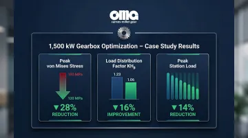
FEA results closely matched AGMA 927 analytical predictions, confirming the analytical method's reliability for practical gearbox design.
Complementary Crowning Techniques
Helix modification handles deflection under load; longitudinal crowning addresses what modification alone cannot — real-world misalignment and mounting errors. Crowning adds a deliberate convex profile along the tooth face to prevent edge contact when installation tolerances fall short of ideal. Research published in MDPI Applied Sciences found that logarithmic crowning reduced transmission error area by 21% under extreme 0.2° misalignments compared to conventional circular or parabolic crowning, successfully preventing edge contact singularities.
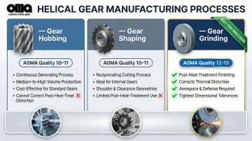
Manufacturing Process Selection: Hobbing, Shaping, and Grinding
The manufacturing process determines maximum achievable AGMA quality grade, surface finish, and whether post-process corrections are possible. This decision should be made in parallel with design—not after.
Gear Hobbing
Process characteristics:
- Continuous generating process for medium-to-high volume production
- Achieves AGMA quality grades up to approximately AGMA 10–11
- Cost-effective for industrial, mining, and agricultural applications
- Cannot correct heat-treat distortion
Carnes-Miller Gear produces helical gears through hobbing up to 200mm pitch diameter, with helix angles up to ±45°, achieving AGMA 10 on shaped and hobbed gears.
Gear Shaping
Process characteristics:
- Reciprocating generating process suited for internal gears and gears close to shoulders
- Achieves AGMA quality grades comparable to hobbing (up to AGMA 10–11)
- Preferred when gear geometry prevents hobbing tool clearance
- Like hobbing, cannot correct heat-treat distortion after processing
Gear shaping complements hobbing in a full-service shop—each process handles geometries the other cannot, giving engineers more design flexibility without sacrificing quality grade.
Gear Grinding
Process characteristics:
- Post-heat-treatment finishing process removing thermal distortion
- Achieves AGMA 12–13 quality grades
- Essential for aerospace, defense, medical, and high-speed power transmission
- Delivers superior surface finish critical for EHD lubrication
Carnes-Miller Gear's gear grinding capabilities extend to 400mm diameter, supporting AGMA 13 quality on ground gears. This covers the full production range from blank to finished gear within a single facility.
Modern grinding economics: Vitrified Cubic Boron Nitride (cBN) wheels yield 2,200–2,500 parts per dress compared to 40–80 for conventional aluminum oxide wheels, cutting per-part costs in high-volume environments.
The Integration Advantage
A job shop with complete in-house capabilities—blanking, hobbing, shaping, heat treatment, grinding, and inspection—eliminates inter-process handoffs that introduce dimensional variation. For tight-tolerance applications, that control matters: a gear that leaves and re-enters the shop between operations picks up fixturing error at every transfer. Keeping all steps under one roof removes that variable entirely.
Heat Treatment and Distortion Control
Heat treatment processes—case hardening, carburizing, or through-hardening—dramatically increase surface hardness, improving pitting resistance and bending fatigue life. However, thermal gradients during quenching introduce dimensional distortion in tooth geometry and helix angle.
Consequences of Uncorrected Distortion
Heat treat distortion creates:
- Deviation from designed helix angle
- Pitch error and runout
- Compromised tooth contact patterns
- Localized stress concentrations even in well-designed gears
The Remediation Approach
Post-heat-treatment grinding restores geometry to specification. However, grinding introduces trade-offs:
Benefits:
- Corrects thermal distortion
- Achieves tight tolerances
- Enables AGMA 12–13 quality grades
Penalties:
- Removes beneficial compressive residual stresses induced by carburizing (averaging 40 ksi reduction for 0.009" grind depth)
- Introduces risk of grinding burn if not properly controlled
Minimizing Distortion at the Source
Single-piece Low-Pressure Carburizing (LPC) with High-Pressure Gas Quenching (HPGQ) reduces helix angle variation standard deviation by 45% compared to batch processing, allowing gears to meet tighter tolerances directly out of heat treat and minimizing required grind stock.
For complex or high-value gear blanks, recognizing salvageable distortion before scrapping a part is where shop experience matters most. Carnes-Miller Gear's in-house nital-etch testing and distortion salvage capabilities reduce scrap rates while protecting the cost already invested in difficult blanks.
Surface Finish, Lubrication, and AGMA Quality Standards
Surface finish directly impacts gear performance by influencing sliding friction, operating temperature, lubricant film life, and resistance to micropitting and scuffing.
Surface Finish and EHD Lubrication
Finer surface finish enables elastohydrodynamic (EHD) film formation at the tooth interface. The specific film thickness (λ ratio)—the ratio of EHD film thickness to composite surface roughness—determines lubrication regime:
- λ < 1: Boundary/mixed lubrication with asperity contact, high friction, micropitting risk
- λ > 2: Full EHD lubrication with minimal asperity contact
NASA research on case-carburized aerospace gears demonstrated that reducing surface roughness from standard ground finish (Ra 0.4 µm) to isotropic superfinish (Ra 0.07 µm) increased surface fatigue life by a factor of four by achieving full EHD lubrication.
AGMA Quality Grades
AGMA grades define tolerances for pitch, profile, lead, and runout. The industry transitioned from legacy ANSI/AGMA 2000-A88 (higher numbers = better quality) to current ANSI/AGMA 2015-1-A01 (lower numbers = better quality).
Quality grade selection:
- AGMA 10–11 (legacy Q8–Q11): Achievable through hobbing; suits most industrial and heavy equipment applications
- AGMA 12–13 (legacy Q12–Q13): Requires grinding; specified for aerospace, defense, and medical applications where tight tolerances and superior surface finish are non-negotiable
NASA-STD-5017B explicitly states that critical spaceflight applications should consider "AGMA quality level 12 or better."
Carnes-Miller Gear offers AGMA 10 on shaped and hobbed gears and AGMA 13 on ground gears, with in-house nital-etch testing to detect and reject grinding burns that compromise surface integrity.
Grinding Burn Detection
Achieving AGMA 12–13 requires grinding — but aggressive post-heat-treat grinding introduces its own risk. Localized overheating (grinding burn) tempers the case-hardened surface and converts beneficial compressive residual stresses into damaging tensile residual stresses.
Nital-etch inspection per ISO 14104 or SAE AMS 2649D uses dilute nitric acid (3–5%) that darkens over-tempered areas. Inspectors can visually identify compromised surface integrity before the gear enters service.
Lubrication Considerations
Helix angle and surface finish together determine EHD film formation. When specifying lubrication for an optimized gear set, designers should account for:
- Pitch line velocity — higher speeds require lower-viscosity oils to maintain film integrity
- Surface finish (Ra) — finer finishes support thinner films; superfinished gears can operate reliably at lower viscosity grades
- Flash temperature — a key scuffing risk indicator, calculated per AGMA 925-A03
- Specific film thickness (λ ratio) — target λ > 2 for full EHD lubrication in demanding applications
Frequently Asked Questions
What is the best helix angle for a helical gear?
The optimal helix angle depends on your application's speed, load, noise requirements, and axial thrust constraints—so there's no single right answer. Typical ranges are 15°–20° for stability-sensitive applications and 30°–45° for smooth, high-speed power transmission.
How does helix angle affect axial thrust in helical gears?
Axial thrust increases with helix angle, proportional to the tangent of the helix angle (Wa = Wt × tan β), requiring appropriately rated thrust bearings. Double-helical (herringbone) designs eliminate net axial thrust by using opposing hand helices.
What AGMA quality grade is needed for aerospace helical gears?
Aerospace and defense applications typically require AGMA 12–13 (legacy Q12–Q13), which requires gear grinding after heat treatment to achieve.
How does gear grinding improve helical gear performance compared to hobbing alone?
Grinding removes heat treat distortion, achieves significantly finer surface finish, and delivers higher AGMA quality grades—reducing noise, improving contact pattern uniformity, and extending gear service life in demanding applications.
What causes premature wear in helical gears?
Main causes include incorrect helix angle leading to edge loading, poor surface finish promoting micropitting, inadequate lubrication breaking down the EHD film, and heat treat distortion creating localized contact stress concentrations.
Can a helical gear be salvaged after heat treatment distortion?
Yes, post-heat-treatment grinding can restore geometry within specification in many cases, depending on how severe the distortion is. An experienced manufacturer can evaluate the gear and often avoid costly scrap of high-value blanks.