Introduction to Advanced Helical Gear Grinding
When a helicopter transmission fails mid-flight or a medical surgical robot loses positioning accuracy, the consequences are catastrophic. Manufacturers in aerospace, defense, and medical device sectors face a persistent challenge: achieving tolerances measured in microns—precision that cutting processes alone cannot deliver.
Helical gear grinding bridges this gap. It's the specialized abrasive finishing operation that achieves AGMA quality levels 10-13 (under legacy standards) or accuracy grades A2-A6 (under current ISO 1328-1:2013 and ANSI/AGMA 2015-1-A01 standards).
The process removes heat treat distortion and delivers the tolerances critical applications demand. According to ISO 1328-1:2013, these accuracy grades define allowable deviations for profile, helix, and pitch—parameters that determine whether a gear meets requirements or fails in the field.
This article explores the technical realities of helical gear grinding: the methods, challenges, quality standards, and industry applications that demand this level of precision.
TLDR:
- Grinding achieves AGMA 12-13 (A2-A6) precision impossible with cutting alone
- Generating grinding offers higher productivity; form grinding handles complex geometries
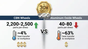
- CBN wheels dress 2,200+ parts vs. 40-80 for conventional abrasives
- Oil-based coolants prevent thermal damage in hardened materials (58-64 HRC)
- Inspection requires CMM analysis, rolling tests, and nital-etch burn detection
What is Helical Gear Grinding?
Helical gear grinding is an abrasive finishing process that uses a rotating grinding wheel to achieve final tooth geometry on helical gears. The grinding wheel follows a helical path synchronized with the gear's rotation, removing material in controlled passes to create precise involute tooth profiles.
Unlike cutting processes that use defined cutting edges, grinding employs thousands of abrasive grains as geometrically undefined cutting edges.
This allows material removal from hardened surfaces (typically 58-64 HRC) while achieving surface finishes and geometric accuracies impossible through hobbing or shaping.
Why Grinding is Essential
Manufacturers perform grinding as a secondary operation after:
- Gear cutting (hobbing or shaping) creates the initial tooth form
- Heat treatment (carburizing, hardening) brings the gear to final hardness
- Thermal distortion from heat treatment alters the geometry
NASA research on helicopter drive systems confirms that carburizing SAE 9310 steel to 58-62 HRC causes significant geometric distortion. Grinding corrects this distortion, restoring profile accuracy, lead accuracy, and pitch precision to meet AGMA Class 12-13 requirements for aerospace applications.
Unique Challenges of Helical Gears
Helical gears present distinct grinding challenges compared to spur gears:
- Helix angle complexity: The grinding wheel must maintain precise angular orientation throughout the helical path
- Lead accuracy requirements: Any deviation in the helical lead creates transmission error and noise
- Three-dimensional tooth geometry: Profile and helix must be corrected simultaneously
- Longer grinding paths: Helical teeth require more wheel travel than straight spur teeth
Tolerance Improvements Grinding Provides
Grinding delivers measurable improvements across four critical parameters:
| Parameter | Pre-Grinding (Cut & Hardened) | Post-Grinding | Improvement |
|---|---|---|---|
| Pitch accuracy | ±15-25 µm | ±3-5 µm | 80% reduction |
| Profile deviation | ±12-18 µm | ±2-4 µm | 75% reduction |
| Lead accuracy | ±20-30 µm | ±4-6 µm | 80% reduction |
| Surface finish | Ra 1.6-3.2 µm | Ra 0.26-0.41 µm | 85% improvement |
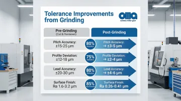
Carnes-Miller Gear achieves AGMA 13 rating on ground gears through precision grinding processes up to 400mm diameter, delivering the tight tolerances aerospace and medical device manufacturers require.
Form Grinding vs. Generating Grinding Methods
Selecting the right grinding method impacts productivity, precision, and cost per part. The two primary approaches—form grinding and generating grinding—use fundamentally different kinematics.
Understanding Form Grinding
Form grinding uses a shaped wheel that matches the tooth space profile, grinding one or two tooth spaces at a time. Operators dress the wheel to the exact negative shape of the gear tooth gap.
Advantages:
- Faster setup for small production runs
- Handles interrupted tooth surfaces and complex geometries
- Works with gears with shoulders or limited clearance
- Flexible for prototype and custom work
Disadvantages:
- Complex wheel dressing requirements
- Limited to specific gear geometries
- Lower accuracy than generating methods (typically AGMA 10-11 vs. 12-13)
- Slower cycle times for production volumes
While form grinding excels in flexibility, generating grinding prioritizes precision and volume efficiency.
Generating Grinding Methods
Generating grinding creates the involute profile through continuous generating motion, similar to how a rack or worm meshes with a gear. The wheel acts as a virtual cutting tool, and the involute form emerges from the kinematic relationship.
Threaded Wheel (Worm) Grinding:
- Continuous generating process with high material removal rates
- Cylindrical grinding worm meshes with the gear blank
- Excellent for helical gears due to natural helix generation
- Dominant method for automotive and high-volume industrial applications
Profile (Disk) Grinding:
- Uses disk-shaped wheels for high precision
- Common in automotive transmission manufacturing
- Achieves AGMA 12-13 accuracy grades consistently
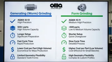
Method Comparison Matrix
| Factor | Generating (Worm) Grinding | Form Grinding |
|---|---|---|
| Precision Level | AGMA 12-13 (A2-A5) | AGMA 10-11 (A6-A8) |
| Production Volume | High (500+ parts) | Low to medium (<500 parts) |
| Setup Time | Longer (specific worm required) | Shorter (wheel dressed to profile) |
| Cycle Time | Faster (continuous indexing) | Slower (discontinuous) |
| Cost Per Part | Lower at volume | Higher overall |
| Geometry Flexibility | Limited (standard involutes) | High (custom profiles, interference) |
According to Gear Solutions Magazine, generating grinding is increasingly replacing profile grinding for batch production due to productivity gains, particularly for gears in the 0.5-10mm module range.
The Helical Gear Grinding Process Step-by-Step
Understanding the grinding cycle reveals why precision requires both advanced equipment and skilled setup.
Pre-Grinding Preparation
1. Gear Blank Inspection
- Verify hardness (58-64 HRC typical)
- Check for heat treat cracks or distortion
- Measure pre-grind geometry to determine stock removal
2. Mounting and Alignment
- Mount gear on precision arbor or mandrel
- Center and secure with appropriate clamping force
- Verify concentricity and perpendicularity
3. Runout Checks
- Measure radial runout (should be <10 µm)
- Check face runout
- Adjust mounting if necessary
The Grinding Cycle
Once preparation is complete, the actual grinding process follows a precise sequence of operations.
Wheel Dressing: The grinding wheel is dressed (sharpened and profiled) using a diamond dressing tool.
For generating grinding, the dresser creates the rack profile on the worm wheel. For form grinding, it creates the exact tooth space negative.
Approach and Engagement: The wheel approaches the gear at a controlled feed rate. Initial contact is verified, and the grinding cycle begins with roughing passes.
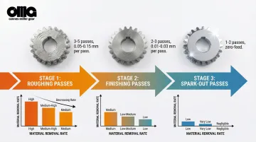
Grinding Passes:
- Roughing passes: Remove bulk material at higher feed rates (0.05-0.15 mm per pass)
- Finishing passes: Fine material removal at reduced feeds (0.01-0.03 mm per pass)
- Spark-out passes: Zero-feed passes that allow the wheel to remove residual material and relieve grinding stresses
A typical pass sequence includes 3-5 roughing passes, 2-3 finishing passes, and 1-2 spark-out passes to achieve the required surface finish and dimensional accuracy.
Coolant Application
Proper coolant management prevents grinding burns—thermal damage that softens the hardened surface. High-pressure, high-flow coolant application is essential. Norton Abrasives research shows that oil-based coolants outperform water-soluble fluids for difficult materials like Inconel 718, preventing burn even at higher material removal rates.
Grinding Wheel Selection
The right wheel selection directly impacts surface finish quality and production efficiency. Carnes-Miller Gear's grinding capabilities accommodate wheels up to 400mm, enabling precise control over the finishing process.
Abrasive Type:
- Aluminum Oxide (Al₂O₃): Conventional abrasive, used for 80-90% of finish grinding, lower cost
- Cubic Boron Nitride (CBN): Second hardest material after diamond, superior for high-volume and hardened steels
Grit Size:
- Coarser grits (60-80) for roughing
- Finer grits (90-125 µm / 120-170 mesh) for finishing to achieve Ra 0.26-0.41 µm surface finish
Bond Type:
- Vitrified bonds (ceramic) for porosity and dressability
- Resin bonds for some CBN applications
Wheel Geometry:
- Worm wheels for generating grinding
- Disk or cup wheels for form grinding
Achieving Precision: Quality Standards and Inspection
Measurable standards define precision, and rigorous inspection verifies it.
AGMA Quality Levels Explained
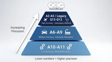
The gear industry has transitioned from the legacy AGMA 2000-A88 "Quality Numbers" (Q-numbers) to the current ANSI/AGMA 2015-1-A01 and ISO 1328-1:2013 "Accuracy Grades" (A-grades). Under the new standards, lower numbers indicate higher precision (opposite of the old system).
Accuracy Grade Ranges:
- A2-A5: High accuracy (equivalent to legacy Q12-Q13) — aerospace, medical devices
- A6-A9: Medium accuracy — industrial, automotive
- A10-A11: Low accuracy — general machinery
High-accuracy grades per ISO 1328-1:2013 require measurement of:
- Cumulative pitch deviation
- Single pitch deviation
- Total profile deviation
- Total helix deviation
- Form and slope components for each parameter
Grinding enables achievement of A2-A5 (legacy Q12-Q13) levels that are impossible with cutting processes alone.
Critical Quality Parameters
Achieving these grades requires control of specific parameters:
Profile Deviation (Fα): Defines how closely the actual tooth profile matches the theoretical involute. Includes total deviation, form deviation (fƒα), and slope deviation (fHα).
Helix Deviation (Fβ): Quantifies the accuracy of the helical lead. Critical for helical gears to ensure proper tooth contact and load distribution.
Pitch Deviation (Fp, fp):
- Cumulative pitch deviation (Fp): Total error over 360°
- Single pitch deviation (fp): Variation between adjacent teeth
Surface Finish (Ra): Average surface roughness. Ground gears typically achieve Ra 0.26-0.41 µm, compared to Ra 1.6-3.2 µm for cut gears.
Tooth Contact Pattern: Visual or pressure-sensitive film analysis showing where gear teeth make contact. Proper contact pattern indicates correct geometry.
Inspection and Quality Control Methods
CMM (Coordinate Measuring Machine) Inspection: Gear measuring centers use 3D scanning to verify all elemental parameters against ISO/AGMA standards. Software generates comprehensive reports showing deviations from nominal geometry.
Nital-Etch Testing: ISO 14104 specifies the nital-etch procedure for detecting grinding burns. A chemical etch reveals surface temper and re-hardening caused by excessive grinding heat. Carnes-Miller Gear maintains in-house nital-etch testing capability to verify that their grinding processes don't compromise material integrity.
Functional Rolling Tests:
- Single-flank test: Rolls the gear against a master gear at designed center distance, measuring transmission error
- Double-flank test: Rolls gears in tight mesh (no backlash) to measure composite errors
These combined methods provide complete verification that ground gears meet specification.
Common Grinding Challenges and Solutions
Precision gear grinding operates within tight tolerances where even minor process variations cause costly failures. Understanding these common challenges—and implementing proven mitigation strategies—separates successful production runs from scrap bins.
Grinding Burns and Thermal Damage
Thermal damage occurs when excessive heat alters the metallurgical structure of gear teeth, compromising strength and performance. Common causes include:
- Excessive heat generation from high material removal rates
- Inadequate coolant flow or improper coolant type
- Dull or glazed grinding wheels
- Incorrect grinding parameters (speed, feed, depth)
Prevention strategies focus on heat management:
- Use CBN wheels that transfer only ~4% of heat to the workpiece (vs. ~63% for aluminum oxide)
- Apply high-pressure, high-flow oil-based coolant
- Maintain proper wheel dressing intervals
- Optimize grinding parameters for material hardness
Early detection through nital-etch testing per ISO 14104 reveals burn before parts reach assembly. Manufacturers like Carnes-Miller Gear perform in-house nital-etch testing to catch thermal damage during production rather than after customer delivery.
Wheel Loading and Glazing
While thermal damage affects the workpiece, wheel condition directly impacts process stability and surface quality. Wheel loading occurs when metal particles embed in the abrasive structure, while glazing happens when abrasive grains wear flat.
Recognition signs include:
- Increased grinding forces and vibration
- Deteriorating surface finish
- Burning or discoloration on gear teeth
- Increased grinding temperatures
Corrective actions depend on wheel type and severity:
- Reduce dressing intervals
- Select wheels with more open structure (higher porosity)
- Switch to oil-based coolant
- For CBN wheels: dress every 2,000+ parts instead of every 40-80 parts for conventional wheels
Norton Abrasives data demonstrates CBN wheels can produce 2,200-2,500 parts per dress compared to 40-80 for aluminum oxide, dramatically reducing non-productive dressing time.
Lead and Profile Errors
Dimensional accuracy determines whether ground gears meet AGMA tolerance classes. Lead errors (axial deviations along the tooth) and profile errors (involute form deviations) stem from multiple sources:
- Machine calibration drift
- Wheel wear changing effective diameter
- Improper setup or work-holding
- Thermal growth during grinding cycle
Correction strategies for maintaining AGMA 13 tolerances:
- Implement closed-loop manufacturing: measure finished gears on CMM and feed corrections back to grinding machine
- Compensate for wheel wear through automatic diameter measurement
- Control thermal stability in the grinding environment
- Re-calibrate machines regularly using certified master gears
Material and Design Considerations for Helical Gear Grinding
Material selection impacts grinding cycle time, wheel wear, and final quality. Choosing incompatible materials or designs can increase costs by 30-40% through extended cycle times and premature tooling replacement.
Optimal Material Hardness Ranges
Typical Range: 58-64 HRC after heat treatment
Why This Range:
- Below 58 HRC: Material may not require grinding; hobbing or shaping may suffice
- 58-62 HRC: Optimal balance of hardness and grindability
- Above 64 HRC: Increased grinding difficulty, slower material removal, higher wheel wear
According to research on case-hardened gears, aerospace applications often specify 60 HRC minimum for SAE 9310 steel to ensure adequate load capacity and wear resistance.
Material Properties and Grinding Parameters
Once you've confirmed hardness compatibility, match your grinding approach to the specific material.
Hardened Steels (58-64 HRC):
- Use CBN (cubic boron nitride) wheels for efficient material removal
- Oil-based coolant recommended for thermal control
- Moderate feeds and speeds balance productivity with surface finish
Superalloys (Inconel, Waspaloy): Specialized wheel specifications required due to work hardening characteristics. Oil-based coolant is mandatory to prevent thermal damage. Expect 40-60% lower material removal rates compared to standard steels.
Case-Hardened Alloys (8620, 9310):
- Standard grinding parameters apply
- Monitor case depth continuously to avoid grinding into soft core
- Case depth: 0.5-1.5mm
Design Features That Impact Grindability
Adequate Root Clearance: Generating grinding requires runout clearance for the worm wheel. Insufficient clearance forces the use of form grinding or special tooling.
Undercut Requirements: Proper undercut at the tooth root prevents interference and allows complete grinding of the active profile.
Helix Angle Limitations: Extreme helix angles (>45°) may exceed machine kinematic limits or require specialized setups.
Tip Relief and Crowning: These intentional profile modifications must be programmed into the grinding cycle and verified during inspection.
Industries and Applications Requiring Helical Gear Grinding
High-precision ground helical gears aren't optional in certain applications—they're required for performance and safety.
Aerospace
Applications:
- Helicopter main transmissions and tail rotor gearboxes
- Turbine engine accessory drives
- Actuator gears for flight control surfaces
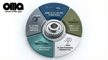
Requirements: AGMA Class 12-13 (A2-A5) precision using materials like VIM-VAR Pyrowear 53 or SAE 9310 carburized to 60+ HRC.
NASA research on helicopter drive systems confirms these precision levels are required to handle pitch line velocities exceeding 15,000 ft/min while minimizing noise and vibration.
Why Grinding Matters: Flight safety depends on gear reliability. Grinding ensures load capacity, fatigue life, and noise levels meet certification requirements.
Defense Systems
Applications:
- Tank and armored vehicle transmissions
- Naval propulsion gearboxes
- Fire control system gears
Requirements: Extreme durability under shock loads and harsh environments. Military specifications often require AGMA Class 11-12 precision with case-hardened alloys like AISI 4340 or nitrided steels.
Ground gears provide the surface integrity and geometric accuracy needed for reliable operation in combat conditions where failure isn't an option.
Medical Devices
Applications:
- Surgical robotic systems
- CT and MRI scanner positioning gears
- Precision pump drives for drug delivery
Requirements: Smooth, quiet operation with high positioning accuracy. In surgical robotics, positioning errors below 0.1mm are critical—ground helical gears eliminate transmission error that would compromise patient safety.
Medical imaging systems similarly demand vibration-free operation. Even minor transmission errors create artifacts in CT or MRI scans, making ground gears essential for diagnostic accuracy.
Automotive
Applications:
- Electric vehicle (EV) transmission gears
- High-performance internal combustion engine transmissions
- Differential gears
Requirements: EV applications demand extreme noise reduction since there's no engine noise to mask gearbox whine. Ground gears reduce transmission error, directly lowering NVH (noise, vibration, harshness). A 3-5 dB reduction in gear noise significantly improves perceived cabin quality.
Industrial Machinery
Applications:
- Turbo-compressor gearboxes
- Power generation gears (35-100 MW)
- High-speed machine tool drives
Requirements: Efficiency and durability under continuous load. Ground helical gears provide the precision needed for optimal efficiency and extended service life. In power generation, every 0.5% efficiency gain translates to substantial cost savings over a 20-year operating life.
These demanding applications across aerospace, defense, medical, automotive, and industrial sectors share a common requirement: precision grinding is the only manufacturing method that delivers the geometric accuracy and surface finish needed for reliable, long-term performance.
Frequently Asked Questions
What is the difference between form grinding and generating grinding for helical gears?
Form grinding uses a shaped wheel to grind one or two tooth spaces at a time, while generating grinding creates the involute through continuous motion like a rack meshing with the gear. Generating methods achieve higher precision (AGMA 12-13) with better productivity for production volumes.
What AGMA quality levels can helical gear grinding achieve?
Grinding typically achieves AGMA 10-13 quality levels under legacy standards (or A2-A6 accuracy grades under current ISO 1328-1:2013). AGMA 12-13 (A2-A5) represents the highest precision grades suitable for aerospace and medical applications where tolerances are measured in single-digit microns.
How do you prevent grinding burns on helical gears?
Prevention requires high-pressure oil-based coolant, grinding parameters matched to material hardness, regular wheel dressing, and CBN wheels that minimize heat transfer. Nital-etch testing per ISO 14104 verifies surface integrity.
When should you choose grinding over hobbing for helical gears?
Choose grinding when high precision (AGMA 11+ or A6 and better) is required, after heat treatment to correct thermal distortion, when superior surface finish (Ra <0.5 µm) is needed, or when the application demands minimal transmission error for noise reduction or positioning accuracy.
What materials are best suited for helical gear grinding?
Hardened steels in the 58-64 HRC range are ideal, including case-hardened alloys like SAE 8620 and 9310. Proper heat treatment to achieve target hardness is essential before grinding. Superalloys like Inconel can be ground but require specialized parameters and oil-based coolants.
How long does the helical gear grinding process take?
Small gears (25-50mm diameter) typically grind in 3-5 minutes, while large precision gears (200-400mm) require 30-90 minutes or more. Generating grinding is faster than form grinding for production volumes.
Need precision helical gear grinding for your critical application? Carnes-Miller Gear provides grinding services up to 400mm diameter, achieving AGMA 13 ratings with in-house nital-etch testing to verify quality. Contact their technical team at 704-888-4448 or dan@cmgear.us to discuss your specifications.