Introduction
Helical gear hobbing is a continuous, generative cutting process: a helical hob rotates in synchronized timing with a gear blank, generating angled tooth profiles through coordinated multi-axis movement. For engineers and OEM procurement leads in aerospace, defense, medical, and heavy equipment manufacturing, the process directly determines gear accuracy, load capacity, noise levels, and service life in high-performance drivetrain systems.
Many organizations struggle with selecting the right gear manufacturing method and understanding when hobbing alone suffices versus when post-hob grinding becomes necessary. According to industry data, properly executed helical gear hobbing can achieve AGMA Quality Grade 10, but heat treatment introduces distortion that often requires corrective grinding to restore dimensional accuracy. That tradeoff directly shapes both production cost and final gear performance.
This article covers how helical gear hobbing works mechanically, what governs output quality, and where the process reaches its practical limits — so technical readers can apply that knowledge, not just recognize the terminology.
Key Takeaways
- Helical gear hobbing synchronizes hob and blank rotation while differential feed generates the helix angle continuously
- Preferred for volume production because it balances cycle time, tooth profile accuracy, and tooling cost better than milling or shaping
- Hob installation angle follows ω = β ± λ, combining the hob lead angle and gear helix angle
- Five factors drive output quality: hob condition, machine rigidity, differential calibration, workholding accuracy, and cutting parameters
- Gears above AGMA Grade 10 — particularly after heat treatment — require post-hobbing grinding
What Is Helical Gear Hobbing?
Helical gear hobbing is a subtractive, generative machining process where a multi-fluted rotary cutting tool (the hob) and a gear blank rotate together on coordinated axes. The hob progressively generates tooth flanks across the full face width in a single continuous pass.
The resulting tooth form isn't a direct copy of the hob's profile — it emerges from the kinematic relationship between hob and workpiece.
How Helical Hobbing Differs from Spur Gear Hobbing
Producing helical teeth requires an additional synchronized differential motion. The blank must rotate slightly faster or slower than the base indexing ratio to generate the helix lead. This is achieved via the machine's differential change gear train on conventional hobbers or through CNC axis interpolation on modern equipment.
How Hobbing Compares to Related Processes
- Gear milling uses a single form cutter that machines one tooth space at a time — slower and less consistent for production quantities
- Gear shaping suits internal gears or shoulder-obstructed blanks well, but a reciprocating cutter introduces inherent dead time between strokes
- Hobbing is faster and more accurate for external helical gears in medium-to-high production volumes
Why Helical Gear Hobbing Is Preferred in Precision Manufacturing
Production Efficiency Advantage
Hobbing is a continuous-cut process that generates all teeth progressively in one or two passes. That alone puts it ahead of single-tooth methods on cycle time. Dry hobbing with HSS hobs operates at 120-250 m/min, which is 1.5 to 2 times the speed of conventional wet hobbing (80-120 m/min). The continuous cutting action eliminates the reciprocating dead time inherent in shaping, compounding time savings for batch production.
Tooth Geometry Advantage
The generative cutting action produces an involute profile mathematically defined by the relative motion of hob and blank, not by the form of a single cutter. This yields:
- Tighter tooth-to-tooth spacing consistency
- Superior lead accuracy across the gear face width
- Profile fidelity that holds up in aerospace, defense, and industrial drivetrain applications — where geometry errors translate directly into noise and fatigue failure
All teeth are formed by the same continuous hob-workpiece kinematic relationship, unlike form milling where each tooth space is cut individually with potential index error accumulation.
Quality Rating Achievable
Properly executed helical gear hobbing achieves AGMA Class 8-10 accuracy levels (per AGMA 2000-A88 numbering). Carnes-Miller Gear has produced to AGMA Quality Grade 10 on hobbed and shaped gears since their founding in 1973. At that rating, gear sets run quietly and resist fatigue in load-intensive environments — mining equipment, rail drives, and agricultural machinery among them.
Hobbing has a practical ceiling, though. For tighter tolerances — AGMA Class 11-13 (old numbering) or A5-A2 on the AGMA 2015 reversed scale — manufacturers typically add grinding or honing after hobbing to close the gap.
How Helical Gear Hobbing Works
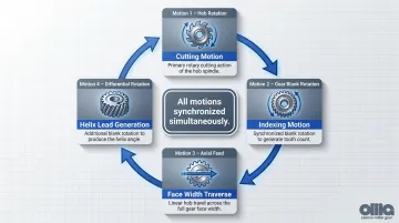
The hobbing machine coordinates three primary motions simultaneously:
- Hob rotation (cutting motion)
- Gear blank rotation (indexing motion)
- Axial feed of the hob across the blank face
For helical gears, a fourth motion is added: differential rotation to the blank that generates the helix lead as the hob traverses.
A hob is a cylindrical cutting tool with helically arranged cutting teeth ground to an involute rack form. Its thread lead angle (λ) and hand of helix must be factored into setup — the hob acts as an involute rack meshing with the gear blank throughout the cut.
Step 1: Hob Selection and Pre-Setup
Hob selection is driven by the gear's normal module (not transverse module), normal pressure angle, and helix angle. Hob hand — right-hand or left-hand — must match the gear's helix direction, which in turn determines whether the installation angle is additive or subtractive.
With the hob selected, workholding becomes the next critical variable. The gear blank must be accurately centered and supported to prevent axial or radial runout — any error here translates directly into lead error and tooth spacing deviation in the finished gear. Blank preparation quality (runout, perpendicularity of bore to face, surface condition) is consistently the overlooked factor when troubleshooting gear accuracy problems.
Step 2: Hob Installation Angle Adjustment
With the blank secured, the hob spindle must be physically tilted to align the hob thread with the gear's tooth direction. The installation angle formula is:
ω = β ± λ
Where ω = hob installation angle, β = helix angle of the gear, and λ = lead angle of the hob.
The sign depends on hand relationship:
| Hob/Gear Relationship | Formula |
|---|---|
| Same hand (e.g., RH hob → RH gear) | ω = β − λ |
| Opposite hand (e.g., RH hob → LH gear) | ω = β + λ |
For spur gears (β = 0°), the hob is simply set to its own lead angle λ.
After setting the installation angle, a light trial pass is made on the blank. The tooth trace is inspected to confirm the helix angle before committing to full depth cutting. This verification step is not optional — it is the most critical quality gate in the hobbing process.
Step 3: Differential Setup and Synchronized Cutting
With the helix angle confirmed, the differential mechanism can be configured. On conventional hobbers, a differential change gear train superimposes an additional rotational correction on the gear blank as the hob traverses axially — causing the blank to rotate slightly more or less per hob tooth engagement than pure indexing alone, generating a continuously helical tooth profile.
Calculation precision matters here. Using a rational fraction for the C constant (e.g., 1403/39 instead of 35.974) is 8.88 times more accurate than the decimal method, reducing feed error from 0.000202" to 0.000000071" — well below the Barber-Colman reference threshold of 0.000015" for maximum allowable feed error.
Modern CNC hobbing machines replace mechanical change gear trains with electronic axis coupling (electronic gearbox), eliminating backlash-induced errors from physical change gears entirely.
During the cutting pass itself:
- Hob feeds axially across the full face width while both hob and blank rotate in continuous synchronization
- Climb vs. conventional milling direction affects surface finish and tool life
- Cutting depth and feed rate must be controlled to prevent profile errors, surface damage, or excessive tool wear
Step 4: Post-Hobbing Inspection
Once cutting is complete, each gear is evaluated against five key parameters:
- Tooth spacing error
- Lead deviation
- Profile form error
- Pitch circle runout
- Surface finish (Ra)
Typical instruments include gear measuring centers, lead checking fixtures, and surface profilometers.
Inspection results determine the path forward:
- Gears meeting dimensional requirements may proceed directly to heat treatment if specified
- Gears intended for higher AGMA grades require gear grinding after heat treatment to correct thermal distortion
- Carnes-Miller Gear provides gear grinding to AGMA 13 on ground gears up to 400mm in diameter — making the combination of hobbing and grinding the standard approach for high-precision helical gear production
Key Factors That Affect Helical Gear Hobbing Quality
Hob Condition and Geometry Accuracy
A worn, chipped, or improperly re-sharpened hob directly degrades tooth profile accuracy and surface finish.
Coating performance:
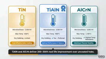
| Coating | Microhardness (HV) | Max Service Temp (°C) | Dry Hobbing Suitability |
|---|---|---|---|
| TiN | 2,300 | 600 | Limited (oxidizes above 600°C) |
| TiAlN | 3,300 | 900 | Yes — preferred for production |
| AlCrN | 3,200 | 1,100 | Highest temperature resistance |
Key findings:
- TiAlN and AlCrN coatings deliver 200-300% tool life improvement over uncoated hobs
- Enable 30-50% increases in cutting speed and feed rate
- PVD coating thickness of 1-4 µm retains sharp edges
- For helical gears with large helix angles or large modules, hob wear accelerates due to higher cutting forces
HSS hobs typically produce 500-2,000 gears before requiring resharpening or replacement, depending on material, module, and cutting parameters.
Machine Rigidity and Axis Synchronization Accuracy
Hobbing machines must maintain precise synchronization between the hob spindle and work spindle throughout the entire cutting pass.
Common machine-condition issues affecting gear quality:
- Excessive backlash in hob or work spindle drive trains causes uniform and non-uniform profile waves
- Loose arbor supports produce helix angular errors and breakout errors
- Gash lead error in the hob translates to approximately 2.5 times the resulting taper error on the gear
- Thermal instability from cold startup to operating temperature causes progressive size variation
- Hob saddle gibs out of adjustment produce helix breakout errors and size variation
Backlash in change gears, spindle bearing wear, or vibration from inadequate machine mass all introduce lead errors and profile deviations — particularly problematic in helical gears where errors accumulate along the helix path.
Workpiece Material Properties and Blank Preparation
Harder or more abrasive workpiece materials — such as alloy steels above 30 HRC — require reduced cutting speeds and feeds to prevent tool overload and premature hob wear.
Blank preparation has an equally direct effect on final gear accuracy:
- Runout exceeding 0.001" at the bore transfers directly into tooth spacing error and pitch variation
- Perpendicularity of bore to face affects helix alignment; even minor face tilt introduces lead deviation across the full face width
- Surface condition of the OD and bore affects how securely the blank seats on the arbor, which determines radial repeatability
Gear blank quality is the most commonly overlooked variable when troubleshooting accuracy problems — correcting it upstream eliminates defects that no amount of cutting parameter adjustment can fix.
Cutting Parameters — Feed Rate, Cutting Speed, and Depth of Cut
Cutting speed ranges:
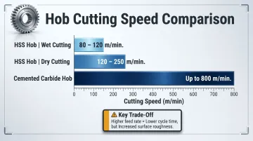
| Hob Type / Method | Cutting Speed Range |
|---|---|
| HSS hob, wet cutting | 80-120 m/min |
| HSS hob, dry cutting | 120-250 m/min |
| Cemented carbide hob | Up to 800 m/min |
Parameter trade-offs:
- Higher feed rates reduce cycle time but increase surface roughness and risk of profile error
- Cutting speed must be matched to hob material (HSS vs. carbide) and workpiece material to avoid premature tool wear or thermal damage
- Increasing cutting speed or feed rate can actually lower workpiece temperature by reducing contact time between the hot cutter and the part — a counterintuitive but well-documented effect
Axial feed rate controls scallop height on the tooth flank — a direct input to surface roughness (Ra). Managing that heat output through feed and speed selection connects directly to how effectively coolant can do its job.
Coolant Application and Thermal Management
Inadequate coolant during hobbing can cause thermal expansion in the workpiece or hob, shifting the effective cutting geometry mid-operation. Directing flood coolant at the cutting zone is standard practice — volume and positioning both matter.
Insufficient coolant is a common root cause of unexpected lead deviations in longer face-width helical gears. Thermal instability affects both the tool and the workpiece, introducing dimensional drift as temperatures fluctuate.
Common Issues, Misconceptions, and Limitations of Helical Gear Hobbing
Most Common Misconception: Hobbing Alone Is Sufficient
In reality, hobbing establishes the tooth geometry, but heat treatment (carburizing, induction hardening) introduces distortion that shifts the gear outside its original tolerance.
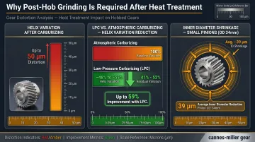
Heat treatment distortion data:
- Carburized gear helix variation can reach 50 microns
- Low Pressure Carburizing (LPC) with high-pressure gas quenching reduces helix variation by 48-59% compared to atmospheric carburizing with oil quench
- Inner diameters can shrink by an average of 39 microns on small pinions (OD 34mm)
Hobbing must be understood as the pre-hardening operation for any gear that will be heat-treated, with gear grinding required afterward to achieve final geometry and surface finish.
Operational Misuse: Assuming a New Hob Guarantees Quality
Even a perfect hob produces a defective gear if:
- Hob installation angle is calculated incorrectly
- Differential change gears are set for the wrong lead
- Blank is not properly centered
Setup verification through trial cut inspection matters more than hob condition alone — it's the step most often skipped and most often responsible for scrapped parts.
When Hobbing Is Not the Right Choice
Hobbing has geometric boundaries — evaluate these at the design stage before committing to process:
- Internal teeth — shaping is preferred
- Shoulder-obstructed gear blanks with limited axial hob travel clearance
- Very large helix angles (typically beyond 45°) that create tool interference issues
- Very small module gears (m < 0.5) where wire EDM or form grinding may be more appropriate
- Helix angles above 45° fall outside the working range of standard universal hobbing machines, which is also the upper boundary recognized by AGMA 2015 for hobbed gears
Within that 0–45° envelope, production helical gears typically run between 15 and 45 degrees — a range where hobbing delivers reliable accuracy across modules from 0.5 to 50 mm and diameters from 5 mm to 10,000 mm. Outside those limits, an alternative process will almost always produce better results at lower cost.
Conclusion
Helical gear hobbing is the most efficient and accurate method for producing external helical gears in production quantities. It generates precise involute tooth profiles through coordinated hob and blank rotation, but quality output depends entirely on correct setup, calibrated differential motion, proper tooling condition, and sound blank preparation.
Understanding helical gear hobbing at an operational level allows engineers and procurement teams to specify gears correctly, evaluate supplier capabilities meaningfully, and recognize when hobbing alone is sufficient versus when a post-hob grinding operation is necessary. In aerospace, defense, industrial, and medical applications, where gear performance directly affects system reliability, getting that call right matters.
For teams sourcing precision helical gears, Carnes-Miller Gear offers over 50 years of hobbing and grinding experience from their 18,000-square-foot facility in Locust, NC. Key capabilities include:
- AGMA 10 quality on hobbed gears
- AGMA 13 quality on ground gears after heat treatment
- Complete turn-key production from blank preparation through post-grind finishing
- In-house inspection equipment for full traceability
Frequently Asked Questions
How does helical gear hobbing work?
Helical gear hobbing uses a synchronized hob-to-blank rotation ratio combined with differential feed motion to continuously generate helical tooth profiles. The hob rotates as a cutting tool while the blank rotates for indexing, and an additional differential rotation produces the helix lead as the hob traverses the face width.
What is the formula for helical gear hobbing?
The hob installation angle formula is ω = β ± λ, where ω is the installation angle, β is the gear helix angle, and λ is the hob lead angle. The differential change gear ratio is calculated from the gear's helix lead and the machine's lead screw pitch, and both must be correctly applied before cutting begins.
What is the difference between hobbing a helical gear and a spur gear?
Spur gear hobbing only requires the hob to be tilted by its own lead angle (λ), while helical gear hobbing additionally requires differential rotational motion superimposed on the blank to generate the helix lead. This makes helical gear hobbing setup more complex and more sensitive to machine calibration errors.
What helix angle range can be produced through hobbing?
Hobbing can practically produce helical gears with helix angles typically up to around 45 degrees, beyond which hob geometry and clearance constraints make the process impractical. Most production helical gears fall in the 15–35 degree helix angle range where hobbing performs optimally.
What AGMA quality grade can be achieved with helical gear hobbing?
Properly executed hobbing achieves AGMA Quality Grade 8–10 (AGMA 2000 numbering), covering most industrial, transportation, and heavy equipment applications. Higher grades — AGMA 12–13 (or A2–A5 in AGMA 2015 numbering) — typically require gear grinding, particularly when heat treatment introduces distortion.
When should helical gear hobbing be followed by gear grinding?
Grinding should follow hobbing in three situations: the gear will be case-hardened or through-hardened (heat treatment distorts tooth geometry); the application requires AGMA Grade 11 or higher; or low noise and high contact ratio are critical — as in aerospace or precision industrial drives.