Introduction
When noise, vibration, and premature wear threaten equipment performance, engineers turn to helical gears. These specialized components dominate manufacturing, automotive, aerospace, and industrial machinery where smooth, quiet operation isn't optional.
Helical gears capture over 45% of the high-performance gear market, chosen for precision applications where noise control and torque density determine system success.
Understanding the mechanical principles behind this smooth operation helps engineers and purchasing managers make better decisions about gear selection, maintenance intervals, and system optimization.
The angled tooth design that defines helical gears enables gradual engagement and superior load distribution. This translates directly to quieter operation and longer service life.
This guide breaks down how helical gears achieve smooth power transmission through their unique design, operational mechanics, and practical applications across industries.
Key Takeaways
- Angled teeth (15-45° helix angle) engage gradually for smoother, quieter operation than spur gears
- 50% higher load capacity through simultaneous engagement across 2-3 teeth
- Ideal for high-speed applications (1000+ RPM) and parallel or non-parallel shaft configurations
- Used in aerospace systems, medical equipment, industrial gearboxes, and precision machinery
What Are Helical Gears?
Helical gears are cylindrical gears with teeth cut at an angle (helix angle) to the gear axis, creating a spiral pattern around the gear circumference rather than straight teeth perpendicular to the axis. This fundamental design difference distinguishes them from spur gears and enables their characteristic smooth operation.
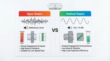
Why helical gears exist: Engineers developed them to solve the operational problems of spur gears—sudden tooth engagement that creates shock loads, noise, and vibration.
By enabling gradual, progressive tooth contact, helical gears eliminate the "hammering" effect that occurs when straight teeth engage abruptly across their entire face width.
What helical gears are NOT:
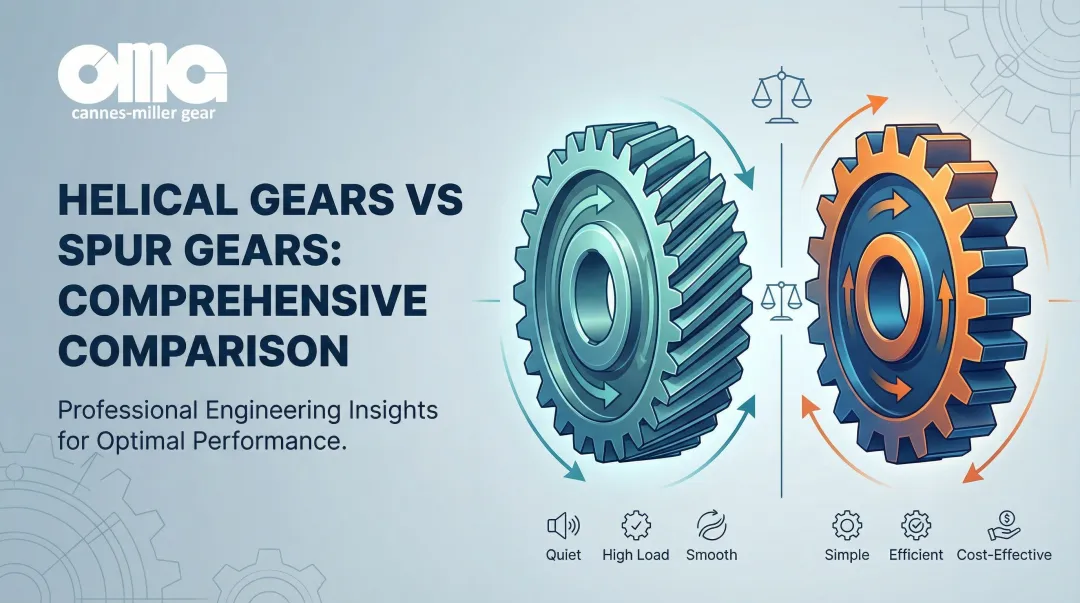
- Spur gears: Straight teeth with abrupt, full-width engagement
- Bevel gears: Conical shape designed for 90° intersecting shafts
- Worm gears: High reduction ratios achieved through sliding contact
Understanding these distinctions helps clarify the two main helical gear configurations used in industrial applications.
Two Main Configuration Types
Parallel helical gears (most common):
- Operate on parallel shafts
- Require opposite helix angles (one left-hand, one right-hand)
- Standard for industrial power transmission
Crossed helical gears:
- Operate on non-parallel, non-intersecting shafts (typically 90°)
- Both gears use the same helix angle direction
- Limited to light-duty applications due to point contact
Helix Angle Selection
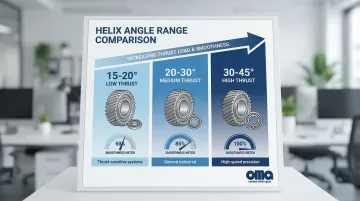
The helix angle (typically 15-45°) directly impacts performance characteristics:
| Helix Angle Range | Thrust Load | Smoothness | Typical Application |
|---|---|---|---|
| 15-20° | Low | Moderate | Applications where minimizing thrust is critical |
| 20-30° | Medium | High | General industrial use (optimal balance) |
| 30-45° | High | Maximum | High-speed automotive transmissions, precision equipment |
Higher angles maximize smoothness but create greater axial thrust requiring robust thrust bearings—a critical design trade-off.
How Do Helical Gears Work?
Helical gears achieve smooth power transmission through a carefully coordinated sequence of gradual tooth engagement, load distribution, and continuous contact that distinguishes them from other gear types.
Tooth Engagement Initiation
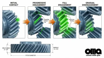
Engagement begins when the angled leading edge of one tooth contacts the angled face of the mating tooth at a single point, rather than the full face-width contact that occurs with spur gears.
As rotation continues, the contact point travels diagonally across the tooth face along the helix angle, progressively increasing the contact area from one end of the tooth to the other.
This gradual engagement means 2-3 teeth are always in partial contact simultaneously—the key to smooth operation. The contact ratio (average number of teeth in contact) reaches 2.0-3.0 for helical gears, compared to just 1.2-1.6 for spur gears.
Progressive Load Transfer
As one tooth pair's contact travels from initial engagement to full engagement and then to disengagement, the next tooth pair is already beginning its engagement cycle, creating continuous, overlapping load transfer.
The angled teeth create a sliding action along the tooth face (in addition to rolling), which helps distribute wear more evenly and maintains a lubricating film between mating surfaces.
This progressive transfer eliminates the shock loading and vibration that occurs when spur gear teeth suddenly engage and disengage with full face-width contact.
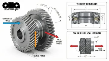
Thrust Load Management
The angled teeth inherently generate axial thrust forces (perpendicular to rotation) in addition to radial and tangential forces. Thrust magnitude increases with helix angle according to the formula:
Axial Thrust = Tangential Load × tan(helix angle)
Thrust management solutions:
- Thrust bearings: Tapered roller or angular contact ball bearings absorb axial forces
- Double-helical (herringbone) gears: Two opposing helix angles cancel thrust forces, eliminating the need for thrust bearings in heavy-duty applications
While thrust loads add complexity, they're the trade-off for the smooth operation and higher load capacity that helical gears provide.
Contact Ratio and Efficiency
Helical gears achieve higher contact ratios than spur gears, typically 2.0-3.0 versus 1.2-1.6, which directly translates to smoother torque transmission and reduced vibration.
The sliding action along tooth faces creates slightly higher friction losses (1-3% efficiency loss) compared to pure rolling contact, but this is offset by reduced shock loads and vibration losses in real-world applications.
Helical gear efficiency typically ranges from 98-99%, slightly lower than spur gears (98-99.5%) due to sliding friction.
Proper lubrication is essential to manage the sliding contact and heat generation, particularly in high-speed or high-load applications. For pitch line velocities exceeding 120 m/s, forced oil circulation becomes necessary.
Noise and Vibration Reduction Mechanism
The gradual engagement and continuous contact eliminate the "hammering" effect of spur gears, where teeth impact creates audible noise and mechanical vibration that spreads through the system. Helical gears typically operate 5-10 dB quieter than equivalent spur gears at standard speeds, with noise reduction reaching 15-20 dB at speeds above 3000 RPM.
Vibration reduction benefits:
- Lower transmission error (deviations in angular velocity)
- Reduced impact forces at mesh engagement (up to 40% reduction)
- Less fatigue stress on bearings, shafts, and housing components
- Extended component life throughout the drivetrain
Where Helical Gears Are Used
Helical gears work best in systems that demand smooth torque delivery, high-speed operation, or noise reduction. You'll find them in intermediate gearbox stages, final drive assemblies, and precision motion control systems.
Operating Environments Where Helical Gears Excel
- Enclosed gearboxes with lubrication systems that maintain film strength
- Continuous-operation applications rather than frequent start-stop cycles
- Load demands exceeding spur gear capacity
- High-speed systems above 1,000 RPM where smooth engagement prevents vibration damage
These environments share a common need: consistent load distribution and gradual tooth engagement that helical designs naturally provide.
Industry Applications
Automotive (41% of market):
- Manual and automatic transmissions for quiet cabin acoustics
- Final drive assemblies
Industrial Machinery (36% of market):
- Speed reducers and gearboxes
- Conveyor systems
- Mixing equipment
Precision Equipment:
- CNC machine tool spindle drives
- Printing press drives
- Elevator hoisting mechanisms
Energy Sector:
- Wind turbine drivetrains
- Power plant cooling towers
Carnes-Miller Gear produces precision helical gears across these sectors with AGMA 10-13 quality ratings. The Locust, NC facility grinds helical gears up to 400mm diameter for aerospace, defense, medical, and industrial applications.

Conclusion
Helical gears achieve smooth power transmission through the fundamental principle of gradual, progressive tooth engagement enabled by their angled tooth geometry. This creates continuous load sharing across multiple teeth, eliminates shock loading, and reduces noise and vibration by 5-10 dB compared to spur gears.
Understanding how helix angle, contact ratio, and thrust loads affect performance helps engineers select appropriate gear types, specify bearing requirements, and establish maintenance schedules that maximize system reliability and lifespan.
These trade-offs reveal the value proposition:
- 20-40% higher manufacturing cost and thrust management requirements
- 50% higher load capacity and significantly quieter operation
- Ideal for applications where smooth power transmission justifies the investment
When your application demands precision helical gears manufactured to exact specifications, Carnes-Miller Gear's in-house grinding capabilities (up to 400mm diameter) and gear cutting services handle projects from prototype to production. Contact their technical team at 704-888-4448 or dan@cmgear.us to discuss your specific requirements.
Frequently Asked Questions
Why are helical gears commonly used in transmissions instead of spur gears?
Helical gears engage gradually rather than abruptly, creating smoother shifting, quieter operation, and the ability to handle the higher torque loads and speeds required in modern transmissions. Their 50% higher load capacity allows for more compact transmission designs.
What is the main difference between helical gears and spur gears?
Helical gear teeth are cut at an angle to the gear axis while spur gear teeth are straight, resulting in gradual versus sudden engagement. Helical gears offer smoother, quieter operation but require thrust bearings to manage axial forces.
What are the disadvantages of helical gears?
Helical gears generate axial thrust loads requiring thrust bearings, have slightly lower efficiency (1-3% loss) due to sliding contact, and are more complex and expensive to manufacture (20-40% higher cost) than spur gears.
How long do helical gears typically last?
Properly designed and lubricated helical gears last 20,000-50,000+ hours under typical conditions, with specialized units exceeding 100,000 hours. Their gradual engagement extends service life compared to spur gears in equivalent applications.
What helix angle is best for helical gears?
Most applications use 20-30° helix angles for optimal balance between smooth operation and manageable thrust loads. Lower angles (15-20°) minimize thrust, while higher angles (30-45°) maximize smoothness.
Can helical gears handle high-speed applications?
Helical gears excel in high-speed applications because their gradual engagement reduces the dynamic loading and vibration that can damage gears at high RPMs. They're ideal for applications above 1000-1500 RPM, with some designs operating effectively above 3000 RPM.