Introduction
Mismatched gear ratios cause premature equipment wear, excessive downtime, and energy inefficiency in industrial machinery. These problems stem from forcing motors to operate outside their optimal efficiency range.
The consequences are serious: motor burnouts, accelerated gear tooth failure, and production bottlenecks that directly impact throughput. A mining operation resolved chronic motor failures by correcting an undersized 10:1 ratio to a 25:1 helical gearbox, achieving seven years of reliable operation.
Research shows that replacing low-efficiency gearing with optimized alternatives can yield energy savings of approximately 15.8% annually, saving thousands of dollars in operating costs for continuous-duty applications.
Understanding these dynamics is critical for optimizing your operations. This article decodes gear ratio fundamentals, explains their impact on performance and efficiency, and provides selection criteria for your manufacturing applications.
Key Takeaways
- Gear ratios control the speed-torque tradeoff: higher ratios (20:1, 50:1) multiply torque for heavy loads while lower ratios (2:1, 3:1) maintain speed
- Matching the right ratio to your application cuts energy consumption by 15-25%
- Proper selection extends equipment lifespan by 30-50%
- Choose based on your load capacity, speed requirements, and duty cycle demands
- Precision manufacturing maintains ratio accuracy under load for millions of cycles
What Are Gear Ratios?
A gear ratio is the relationship between the number of teeth on two meshing gears, expressed as a ratio such as 3:1 or 4.5:1. In manufacturing equipment, gear ratios appear in gearboxes, reducers, and drive systems that transfer power from motors to machinery.
The ratio determines how input speed and torque transform into output performance. This principle affects everything from conveyor systems to CNC spindles.
Core Components That Determine Gear Ratio Performance
Three key elements work together to establish gear ratio performance:
Driver Gear (Input): The driving gear connects to the power source (typically an electric motor). The number of teeth on this gear forms the denominator in ratio calculations. A smaller driver gear with fewer teeth creates a higher gear ratio, multiplying torque while reducing speed.
Driven Gear (Output): The driven gear receives power from the driver and connects to the load. Its tooth count forms the numerator in the ratio calculation. A larger driven gear with more teeth increases the ratio, providing greater torque boost.
Compound gear trains use multiple gear stages to multiply ratios beyond what single-stage systems can achieve. Two 5:1 stages create a 25:1 overall ratio (5 × 5 = 25), enabling extreme torque multiplication for applications like heavy mixing or mining equipment.
How Gear Ratios Affect Mechanical Advantage
Understanding these components reveals the fundamental tradeoff in gear engineering: torque multiplication comes at the cost of speed reduction, and vice versa.
This relationship is governed by physics. Power (the product of torque and speed) remains constant minus efficiency losses.
Basic Calculation Formula:
Gear Ratio = Driven Gear Teeth ÷ Driver Gear Teeth
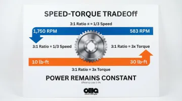
For example, if the driven gear has 60 teeth and the driver has 20 teeth, the ratio is 60 ÷ 20 = 3:1.
Interpreting the Result:
- A 3:1 ratio means output speed is one-third of input speed
- Output torque is three times input torque (minus efficiency losses of 2-5%)
- Motor running at 1,750 RPM produces output speed of approximately 583 RPM
- Input torque of 10 lb-ft produces output torque of approximately 30 lb-ft
This mechanical advantage allows smaller motors to drive larger loads, but the speed penalty must align with production requirements.
Why Gear Ratios Matter for Manufacturing Performance and Efficiency
Gear ratios directly impact four critical operational metrics: power efficiency, equipment longevity, production throughput, and energy costs. Selecting the wrong ratio creates a chain of problems that affect every aspect of manufacturing operations.
Impact on Torque and Load Handling
Higher gear ratios (10:1, 20:1, 50:1 or more) multiply torque, enabling machinery to handle heavy loads in applications like mining crushers, industrial conveyors, and hydraulic presses.
The torque multiplication formula is:
Output Torque = Input Torque × Gear Ratio × Efficiency
For example, a 20:1 ratio with 98% efficiency transforms 50 lb-ft of motor torque into approximately 980 lb-ft at the output shaft.
The Cost of Insufficient Torque: Undersized gear ratios force motors to strain under heavy loads. This causes:
- Motor overheating as windings draw excessive current
- Thermal damage to insulation, leading to premature failure
- Increased mechanical stress on gear teeth, accelerating wear
- Frequent motor burnouts requiring costly replacements
A mining conveyor case study demonstrated these consequences: an undersized 10:1 ratio caused repeated motor failures. Switching to a properly sized 25:1 helical gearbox eliminated the problem, achieving seven years of maintenance-free operation.
Impact on Speed and Production Throughput
Lower gear ratios (2:1, 3:1, 4:1) maintain higher output speeds essential for high-speed manufacturing processes like packaging lines, CNC machining, and automated assembly.
The speed relationship is:
Output Speed (RPM) = Input Speed (RPM) ÷ Gear Ratio
A 1,750 RPM motor with a 2:1 ratio delivers 875 RPM output speed—suitable for applications requiring rapid motion.
The Bottleneck Problem: Over-geared systems (ratios too high for the application) create production bottlenecks:
- Output speed drops below process requirements
- Cycle times increase, reducing units per hour
- Production capacity falls short of demand
- Manufacturers must run equipment longer to meet quotas, increasing energy costs
To address this challenge, CNC spindles often use two-speed gearboxes offering both high-speed ratios (1:1 for finishing operations) and high-torque ratios (3.2:1 for heavy roughing cuts), optimizing performance across different machining tasks.
Impact on Energy Efficiency
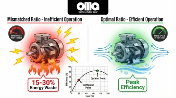
Properly matched gear ratios keep motors operating in their optimal efficiency range, typically between 75% and 100% of rated load. Industrial induction motors achieve peak efficiency in this zone, converting electrical energy to mechanical work with minimal losses.
Research shows that optimizing gear ratios can reduce energy consumption by 15-25% depending on the application. For example, replacing a worm gear reducer (50-80% efficient) with a helical-bevel unit (95%+ efficient) in a 5 HP application saves approximately 6,472 kWh annually—a 15.8% reduction.
How Mismatched Ratios Waste Energy: Mismatched ratios push motors outside their efficiency curve:
- Motors run at low speeds and high torque (below optimal range), converting excess energy to heat
- Excessive current draw increases electrical costs
- Cooling systems work harder to dissipate heat, consuming additional energy
- Annual energy waste can reach $5,000-$50,000 depending on motor horsepower and runtime
The solution is selecting ratios that allow motors to run at or near their rated speed (typically 1,750 or 3,600 RPM for 60 Hz systems) while the gearbox provides the necessary speed reduction and torque multiplication.
Impact on Equipment Longevity and Maintenance Costs
Correct gear ratios distribute mechanical stress evenly across gear teeth, extending component life and reducing maintenance frequency. Loads matching design specifications keep gears within intended stress limits, preventing premature wear.
Precision Manufacturing's Role: Precision-manufactured gears with tight tolerances (AGMA 10-13 ratings in legacy standards, or AGMA A5-A2 in current standards) maintain ratio accuracy over millions of cycles. These quality grades ensure:
- Consistent tooth contact patterns that distribute loads evenly
- Minimal transmission error and vibration
- Reduced localized stress concentrations that cause pitting
- Extended service life in continuous-duty applications
Quantified Benefits:
- Premium materials and precision manufacturing reduce unplanned downtime by 30-50%
- Predictive maintenance combined with precision components cuts downtime by 30%
- Proper ratio selection in the mining conveyor case extended equipment life from months to 7+ years
- Optimized bearing ratios can improve life expectancy by 35% in related rotating components
The business case is clear: investing in correctly specified gear ratios and precision manufacturing pays for itself through reduced maintenance costs and eliminated production losses.

What to Consider When Selecting the Right Gear Ratio
Selecting optimal gear ratios requires analyzing six related factors that connect technical specifications to measurable business outcomes. These considerations vary significantly across industries—aerospace demands different ratio strategies than mining or agricultural equipment.
A systematic approach ensures your gear system delivers maximum efficiency and longevity.
Load Requirements and Duty Cycle
Understanding load characteristics forms the basis for ratio selection. You must analyze three load types:
- Maximum force during startup, shock loads, and emergency stops
- Typical operating force during normal production cycles
- Sudden force spikes from material impacts, jamming, or rapid acceleration
Duty Cycle Considerations:
Continuous-duty applications (24/7 operations like conveyors, compressors, and fans) require conservative ratio selection with higher service factors.
Intermittent-duty equipment (presses, hoists, indexing tables) can use ratios closer to calculated minimums since thermal buildup and fatigue accumulate more slowly.
Operational Impact:
Incorrect load matching accelerates gear tooth failure. Bearing research shows that suboptimal load ratios can reduce component life by up to 42%—the same principle applies to gears.
Undersized ratios cause overload failures, while oversized ratios waste energy and capital.
Service Factors:
AGMA standards recommend service factors based on load characteristics. For example, mining crushers with severe shock loads require AGMA Class III ratings with service factors of 2.0 or higher, meaning the gearbox must handle twice the nominal load.
Speed Requirements and RPM Ranges
Start with your required output speed based on process requirements, then work backward to determine the ideal ratio. This reverse-engineering approach ensures the final system meets production needs.
Calculation Method:
- Identify required output speed (e.g., 200 RPM for a conveyor)
- Determine available motor speed (typically 1,750 RPM for 4-pole motors or 3,600 RPM for 2-pole motors)
- Calculate required ratio: Motor Speed ÷ Desired Output Speed
- Example: 1,750 RPM ÷ 200 RPM = 8.75:1 ratio
Standard Motor Speeds:
- 2-Pole Motors: ~3,600 RPM (high-speed applications)
- 4-Pole Motors: ~1,750 RPM (most common industrial standard)
- 6-Pole Motors: ~1,200 RPM (high-torque, low-speed applications)
KPI Impact:
Optimal speed matching improves throughput efficiency by maintaining consistent production rates. Mismatched ratios force operators to adjust process parameters, run equipment longer, or accept reduced output—all of which increase per-unit production costs.
Efficiency and Power Loss
All gear systems lose energy to friction, with typical losses of 2-5% per gear stage. Ratio selection affects total system efficiency because different gear types and configurations have distinct efficiency characteristics.
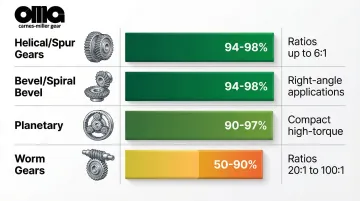
Efficiency by Gear Type:
| Gear Type | Efficiency Per Stage | Best Applications |
|---|---|---|
| Helical/Spur | 94-98% | Parallel shaft, moderate ratios up to 6:1 |
| Bevel/Spiral Bevel | 94-98% | Right-angle drives, moderate ratios |
| Planetary | 90-97% | High torque density, compact installations |
| Worm | 50-90% | High ratios (20:1 to 100:1), self-locking capability |
Multi-Stage Considerations:
Compound gear trains multiply efficiency losses. A three-stage helical gearbox with 98% efficiency per stage has total efficiency of 0.98 × 0.98 × 0.98 = 94.1%.
This configuration allows higher ratios in compact spaces, but the cumulative losses must be factored into energy cost calculations.
Precision Manufacturing's Role:
Tighter tolerances and better surface finish reduce friction losses. Ground gears (AGMA 13 rating in legacy standards) achieve the high end of efficiency ranges because precision tooth profiles minimize sliding friction and ensure optimal contact patterns.
Operational Metric:
High-efficiency gear systems can reduce energy costs by $5,000-$50,000 annually depending on horsepower and runtime.
For a 50 HP motor running 8,000 hours per year, improving system efficiency from 90% to 95% saves approximately $2,000 annually at $0.10/kWh. Scale this across multiple motors in a facility, and the savings compound significantly.
Available Space and Mounting Constraints
Physical space limitations determine whether single-stage or multi-stage gear reduction is feasible. This consideration directly influences ratio selection and gearbox design.
Single-Stage Limitations:
- Spur/helical gears: Practical limit ~6:1 (larger ratios require very large driven gears)
- Bevel gears: Similar ~6:1 limit for right-angle applications
- Worm gears: Can achieve 100:1 in single stage but suffer poor efficiency
Multi-Stage Solutions:
When space allows, multi-stage gearboxes achieve high ratios in manageable packages:
- Two 5:1 stages = 25:1 overall ratio
- Three 4:1 stages = 64:1 overall ratio
- Planetary arrangements provide compact high-ratio solutions
Custom vs. Standard:
Custom gear solutions can achieve required ratios within space constraints that standard gearboxes cannot accommodate.
For example, a custom two-stage helical design might fit where a single-stage unit would require prohibitive space, while maintaining higher efficiency than a compact worm gear alternative.
Material Selection and Durability
Gear material affects load capacity, wear resistance, and how well gears maintain ratio accuracy under stress. The relationship between material properties and ratio performance is direct: harder materials resist deformation under high loads, maintaining precise tooth geometry.
Common Gear Materials:
Case-Hardened Steel:
- Carburizing-grade steel (8620, 9310) with surface hardening
- Provides hard wear-resistant surface (58-63 HRC) with tough core
- Best for high-load, high-cycle applications
- Maintains ratio precision under shock loads
Through-Hardened Steel:
- Alloy steels (4140, 4340) hardened throughout
- Good strength and wear resistance
- Suitable for moderate loads and speeds
- Less expensive than case-hardened alternatives
Bronze Alloys:
- CDA 954 aluminum bronze, CDA 932 bearing bronze
- Excellent for worm wheels (paired with hardened steel worms)
- Self-lubricating properties reduce friction
- Lower strength than steel limits load capacity
Precision Heat Treatment:
AGMA 13 ratings (legacy standard for ground gears) require precise heat treatment and grinding operations. This combination enables gears to maintain ratio accuracy under high loads by:
- Minimizing distortion during heat treatment
- Achieving tight tooth profile tolerances through grinding
- Creating uniform surface hardness for consistent wear patterns
Business Impact:
Premium materials and precision manufacturing reduce unplanned downtime by 30-50% compared to lower-quality alternatives.
The initial cost premium pays for itself through eliminated production losses and reduced maintenance expenses.
Application-Specific Requirements
Different industries have unique ratio needs driven by operational demands, environmental conditions, and performance specifications.
Aerospace:
- Requires lightweight high-precision gears to minimize aircraft weight
- AGMA Q15 quality (legacy standard, equivalent to modern A2) ensures reliability
- Typical applications: fuel pumps, actuators, landing gear systems
- Ratios optimized for power density and fail-safe operation
Mining:
- Needs high-torque ratios (50:1 to 400:1) for crushers, mills, and conveyors
- Heavy shock loads require robust service factors (SF 2.0+)
- Continuous-duty cycles demand exceptional durability
- Ratios prioritize torque multiplication over speed
Medical Equipment:
- Demands quiet operation with precise positioning
- Zero or minimal backlash for surgical robotics and imaging systems
- Often uses harmonic or planetary gears for compact precision
- Ratios optimized for smooth, controllable motion
Reverse Engineering Considerations:
For obsolete equipment, matching original gear ratios is critical for replacement parts. Manufacturers like Carnes-Miller Gear specialize in reverse engineering discontinued components, reproducing exact specifications to maintain system performance without costly equipment replacement.
Custom Manufacturing Advantage:
Off-the-shelf gearboxes force compromises—you accept available ratios, mounting configurations, and efficiency levels. Custom gear solutions optimize for your specific application, delivering the exact ratio, materials, and precision grade your operation requires.

How Carnes-Miller Gear Can Help Optimize Your Gear Ratios
Carnes-Miller Gear's 50+ years of precision gear manufacturing expertise enables custom gear solutions that optimize both performance and efficiency for your specific application.
Since 1973, CMG has helped manufacturers across diverse industries solve complex gear ratio challenges through comprehensive in-house capabilities. Complete control over gear blanking, hobbing, grinding, and broaching ensures precision at every stage—eliminating the quality inconsistencies and delays common with multi-vendor approaches.
Unique Value Propositions:
Precision Quality Standards:
- AGMA 10 rating on shaped and hobbed gears
- AGMA 13 rating on ground spur gears
- Grinding capabilities up to 400mm diameter
- Cutting teeth up to 200mm pitch diameter
Specialized Capabilities:
- Reverse engineering for obsolete equipment (recreating discontinued gears with exact ratio matching)
- Custom gear assemblies for high-end testing equipment
- In-house nital-etch testing detects grinding burns that compromise gear integrity
- Turn-key production from raw material to finished assembly
Industry Expertise: This precision expertise translates across nine distinct sectors: aerospace, defense, medical, industrial, mining, transportation, construction, agricultural, and rail.
CMG understands the distinct ratio requirements each industry demands—from aerospace's lightweight precision to mining's shock-load durability.
Whether you need to optimize ratios in existing equipment through custom replacement gears, design new systems with application-specific ratios, or solve space-constrained installations, Carnes-Miller Gear's engineering team can develop solutions that standard gearboxes cannot accommodate.
Conclusion
Selecting optimal gear ratios isn't about choosing the highest or lowest ratio—it's about matching mechanical advantage to your operational requirements for maximum efficiency and longevity. The right ratio keeps motors in their optimal efficiency range, extends equipment life, and maximizes production throughput.
Precision manufacturing quality is equally important as ratio selection. Key quality factors include:
- AGMA ratings – Higher ratings (AGMA 10-13) maintain ratio accuracy under load
- Surface finish – Smooth finishes reduce friction and wear
- Heat treatment – Proper treatment extends performance life before wear degrades precision
Investing in precision-manufactured gears delivers measurable returns through reduced energy costs, prevented downtime, and extended service life.
Evaluate gear ratio performance periodically as production requirements evolve. Precision-manufactured replacement gears can upgrade existing systems, optimizing ratios without replacing entire gearboxes. Custom gear manufacturers like Carnes-Miller Gear can grind replacement gears to AGMA 13 standards, offering a cost-effective path to improved efficiency and reliability without full gearbox replacement.
Frequently Asked Questions
What is the ideal gear ratio for industrial equipment?
There is no universal "ideal" ratio—the optimal ratio depends on specific application requirements including load characteristics, speed needs, duty cycle, and efficiency targets. Calculate the required ratio based on motor speed (typically 1,750 or 3,600 RPM) and desired output speed, then verify it provides sufficient torque for your load.
How does gear ratio affect efficiency?
Properly matched ratios keep motors in their optimal efficiency range (75-100% of rated load), while mismatched ratios waste 15-30% of input energy as heat and friction. Higher ratios also introduce gearbox losses of 2-5% per gear stage.
Can you change gear ratios in existing equipment?
Yes, gear ratios can be modified by replacing gears with different tooth counts. Custom manufacturers can create replacement gears to optimize existing systems or reverse-engineer obsolete components when original specifications are unavailable, upgrading performance without replacing entire gearboxes.
What gear ratio provides the most torque?
Higher numerical ratios (20:1, 50:1, 100:1 or more) provide greater torque multiplication. The maximum practical ratio depends on space constraints, efficiency requirements, and whether single-stage or multi-stage reduction is used. Multi-stage compound gear trains can achieve ratios exceeding 400:1 for extreme torque applications like heavy mixing or mining crushers.
How do AGMA gear quality ratings relate to gear ratio performance?
AGMA ratings indicate manufacturing tolerance and surface finish quality. Higher precision grades ensure gears maintain their ratio accurately under load by minimizing tooth profile errors. This precision directly affects service life—critical for achieving 100,000+ hour performance in industrial applications.
What's the difference between gear ratio and reduction ratio?
These terms are often used interchangeably in practice. Technically, reduction ratio specifically refers to speed reduction (input RPM ÷ output RPM), while gear ratio is the tooth count relationship (driven teeth ÷ driver teeth). Both express the same mechanical relationship in most applications, though "reduction ratio" emphasizes the speed-reducing function of the gearbox.