CNC gear cutting is a computer-controlled manufacturing process that removes material from a gear blank to generate precise tooth geometry for power transmission. Modern CNC systems enable micron-level tolerances across both high-volume production runs and one-off custom parts. But the process rarely ends at cutting — finishing operations determine whether a gear actually performs to spec in service.
This article covers the primary cutting methods, finishing processes, accuracy factors, machine technology, and a practical framework for choosing the right approach for your application.
Key Takeaways
- Tooth generation gets you close; finishing operations like grinding determine final accuracy and surface quality
- Hobbing suits external spur and helical gears at medium-to-high volumes; shaping and skiving handle internal gears
- Heat treatment improves strength but causes distortion; plan post-treatment finishing allowances into the workflow from the start
- AGMA accuracy requirements should drive method selection, not habit or convenience
- Mismatching method to application adds cost without improving performance
Core CNC Gear Cutting Methods
CNC gear cutting methods fall into two categories. Generation methods create tooth shape through synchronized motion between the tool and workpiece — the tooth profile emerges from the cutting relationship, not the tool shape alone. Forming methods use a cutter whose profile directly matches the tooth gap geometry.
This distinction matters practically: generation methods are faster and more flexible across gear modules, while forming methods can handle profiles that generation tools cannot.
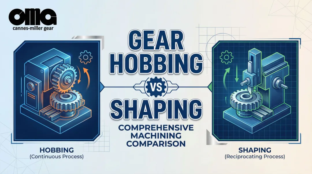
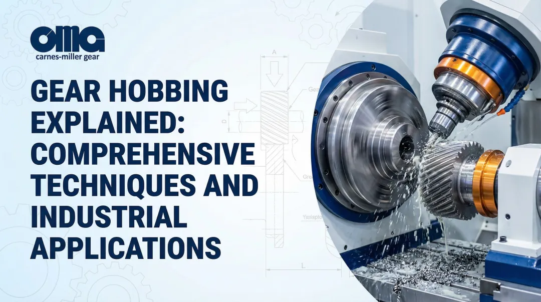
Gear Hobbing
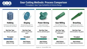
Hobbing is the industry standard for external spur and helical gears. A rotating hob cutter continuously engages the gear blank, generating consistent tooth spacing through synchronized rotation between hob and workpiece. The process is fast, efficient, and adaptable across a wide range of modules and gear types.
For medium-to-high volume external gear production, hobbing is almost always the starting point. Liebherr's hobbing machines handle workpieces from 20mm up to very large diameters, and Gleason's Genesis series covers spur and helical gears up to 400mm.
The key limitation: conventional hobbing is selected for external spur and helical gears where the cutter has clear runout access. Internal gears generally require a different method entirely.
Gear Shaping and Power Skiving
Gear shaping uses a reciprocating pinion-type cutter that generates teeth one space at a time while the cutter and blank rotate together. It's slower than hobbing but handles geometries hobbing can't reach — internal gears, shoulder-adjacent features, and configurations where a hob simply cannot run through.
Power skiving is a higher-efficiency alternative for internal gears. The skiving tool is tilted at a crossing angle relative to the workpiece axis, creating axial relative speed that rapidly removes material in a continuous cutting action. Klingelnberg defines this as a continuously revolving toothing process driven by intersecting tool and workpiece axes.
Gleason positions power skiving as a high-productivity alternative to shaping and, in many cases, hobbing or broaching. For internal ring gears used in planetary systems, skiving offers a significant cycle time advantage — provided batch sizes justify the tooling investment.
Gear Milling and Broaching
Gear milling (form cutting) uses a form cutter or end mill to cut one tooth gap at a time via CNC-controlled indexing. Gear Solutions describes HSS cutters as cost-effective for very low-volume work. The trade-off is productivity — milling is significantly slower than hobbing, which makes it best suited for prototypes, large one-off gears, or custom profiles where dedicated hob tooling isn't economical.
Broaching operates on a fundamentally different principle. A progressive multi-toothed broach forms all teeth in a single pass — making it the fastest internal gear-forming method available. Custom broach tooling is expensive and machine investment is substantial, so the economics only work at scale. Gear Technology frames broaching as the right choice for high-volume power-transmission parts, not a flexible option for job shop work or custom profiles.
At a glance, here's how the four methods compare on flexibility vs. throughput:
- Hobbing: Highest throughput for external spur/helical gears; limited to geometries with hob runout clearance
- Shaping: Slower than hobbing but handles internal gears and tight shoulder clearances
- Power skiving: Fast cycle times for internal gears; requires specialized machine synchronization
- Gear milling: Most flexible for one-off or custom profiles; slowest throughput
- Broaching: Fastest for internal gear production at high volumes; tooling cost limits flexibility
Gear Finishing Processes for Precision and Long-Term Performance
Cutting alone rarely achieves what precision applications require. Tooth profiles cut to nominal dimensions can still exhibit noise, uneven wear, or early failure in service — because cutting operations leave surface irregularities and cannot fully control the contact pattern under load.
Finishing operations correct profile errors, improve surface texture, and refine contact geometry that cutting cannot address.
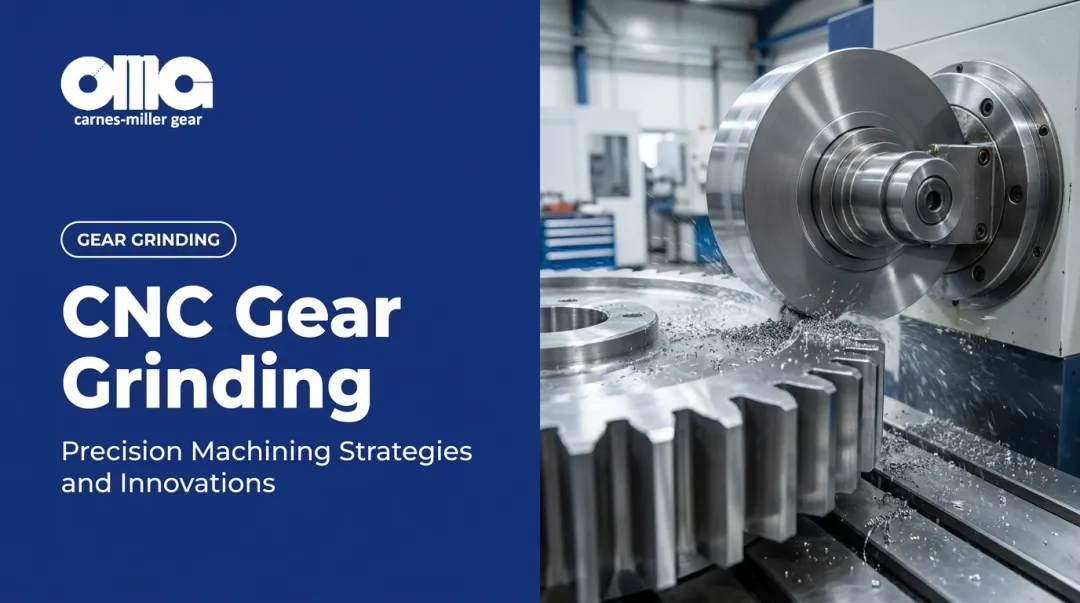
Gear Grinding
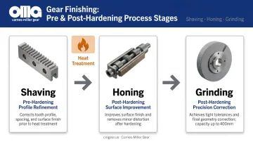
Gear grinding is the highest-precision finishing method available. An abrasive wheel refines the tooth surface after heat treatment, correcting distortion and achieving tight tolerances on profile, lead, and surface finish.
Liebherr reports generating grinding quality of ISO 5, index accuracy of ±20μm, and surface finish of Rz 3–6μm on double helical gears.
Grinding is mandatory for high-speed, high-load, or low-noise applications. It's also the method used to reach the highest AGMA accuracy grades — Carnes-Miller Gear achieves AGMA 13 on ground spur and heat-treated gears, with grinding capacity up to 400mm in diameter.
Liebherr also notes that generating grinding is specifically more resistant to stock variation and heat treatment distortion compared to other finishing methods — a practical advantage when hardened gear distortion is unpredictable.
Gear Honing
Gear honing is a crossed-axis, hard-finishing process that uses pressure and abrasive tools to remove small amounts of material along tooth flanks. The cross-hatch pattern it produces helps retain lubrication on the tooth face — which reduces premature wear under heavy load cycles where surface film breakdown is a failure driver.
Honing corrects minor geometry errors and improves surface texture after heat treatment, but it's not a substitute for grinding when significant distortion correction is needed.
Gear Shaving
Gear shaving removes small amounts of material to improve tooth profile and pitch consistency before hardening. It's fast and cost-effective as a pre-heat-treatment step — but it only works on softer, pre-hardened material.
Because heat treatment follows shaving, any distortion introduced during hardening still requires a hard finishing operation downstream. Shaving improves the geometry you take into heat treatment; it doesn't eliminate the need for post-treatment correction.
Each finishing method fits a different point in the production sequence:
- Shaving — pre-hardening profile refinement, best for cost-effective geometry improvement before heat treat
- Honing — post-hardening surface improvement, suited for minor corrections and lubrication-retaining finishes
- Grinding — post-hardening precision correction, required when tight tolerances or significant distortion must be addressed
Key Factors That Affect CNC Gear Cutting Efficiency and Accuracy
Tooth Geometry and Profile Control
Even small deviations in the involute profile change contact ratio, load distribution, and noise behavior. Gear Technology research on microgeometry confirms that microtopographic variation affects gear performance parameters — meaning nominal involute geometry alone doesn't predict real-world behavior.
Intentional profile modifications — crowning, tip relief, topological corrections — are used to compensate for deflection under load and improve contact patterns. Liebherr's generating grinding machines can produce these topological modifications cost-effectively, making them practical for production runs rather than just prototype work.
Machine Rigidity and CNC Synchronization
Gear cutting is sensitive to spindle deflection, axis backlash, and thermal drift. Liebherr's EMO 2025 platform uses a thermo-symmetric machine bed with integrated coolant circulation and a hydrostatic bearing table to address thermal stability directly.
Synchronization accuracy between rotary and linear axes is equally critical — especially for fine-pitch or hardened gear work. NUM's electronic gearbox system eliminates the mechanical gearbox entirely, using five-axis electronic gear synchronization to maintain accuracy without the backlash and changeover overhead of mechanical systems.
Material Selection and Heat Treatment Behavior
Different steels behave differently through the machining-to-hardening sequence, and those differences compound.
- Case-hardened alloys (carburized and quenched) undergo martensite transformation during hardening, causing 1.37–1.53% linear expansion depending on carbon content, per ASM data
- Through-hardened alloys distort differently based on geometry, grain size, steel cleanliness, and quench uniformity
- Both alloy types require grinding allowance planned before cutting — Klingelnberg's fine grinding data recommends 0.10–0.12mm stock per flank to accommodate heat treatment deviation
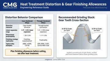
Post-heat-treatment finishing must be built into the process plan from day one — not treated as a correction step when distorted parts come out of the oven.
Tooling Condition and Setup Quality
Worn hobs and misaligned blanks both introduce errors that propagate through an entire production run — worn tooling creates systematic profile deviations, while blank misalignment produces concentricity errors that affect engagement quality throughout the drivetrain.
Setup consistency matters as much as machine capability:
- Blank concentricity and bore runout directly affect tooth engagement quality
- Hob condition determines whether profile errors are random or systematic
- Consistent setup across a batch ensures the grinding allowance is uniform — which matters when a downstream grind must correct heat treatment distortion
CNC Machine Technology and Capabilities for Gear Cutting
Multitasking Machines
Modern CNC multitasking machines consolidate what previously required separate dedicated setups — turning, hobbing, milling, and measurement — into a single fixturing. Mazak's INTEGREX AG integrates gear skiving, hobbing, end milling, and in-process measurement on one platform.
The practical impact on production efficiency is substantial. DMG MORI reports one gearSKIVING case study where a part previously requiring 9 separate setups was completed in 1 setup, with total processing time dropping from 40 minutes to 10 minutes. For small-to-medium batch work where setup changes dominate cycle time, that's a direct cost reduction.
Electronic Synchronization Options
Two synchronization approaches are used in production CNC gear cutting:
| Method | Function | Best Application |
|---|---|---|
| Electronic Gearbox (EGB) | Uses feedback from the cutter spindle to control workpiece rotation | High-precision hobbing; eliminates mechanical gear-change overhead |
| Flexible Synchronization | High-speed synchronization across multiple spindles simultaneously | Gear skiving; multi-stage cutting operations requiring tight cross-axis control |
For skiving specifically, DMG MORI confirms the workpiece and skiving tool must rotate in precise synchronization at a specified crossing angle — making flexible synchronization the gating capability for this process.
Conversational Programming
That synchronization and multitasking complexity doesn't have to translate into complex programming. Mazak and DMG MORI both offer conversational programming interfaces where operators input gear parameters and the system generates NC toolpaths. Typical inputs include:
- Tooth count and module
- Pressure angle and helix angle
- Cutter geometry and feed rates
This reduces programming time significantly and makes gear cutting more accessible in job shop environments — useful when engineers need prototype gears cut without dedicated gear programming staff on hand.
How to Choose the Right CNC Gear Cutting Method
Decision Framework
Match method to application using three variables: production volume, gear geometry, and required accuracy grade.
| Application Profile | Recommended Method |
|---|---|
| External spur/helical, medium-to-high volume | Hobbing |
| Internal gears, ring gears | Power skiving (if synchronization available) or shaping |
| Low volume, prototypes, custom profiles | Gear milling |
| Very high-volume standardized internal forms | Broaching |
| Hardened gears, AGMA 13+ or low-noise required | Grinding (following initial cutting operation) |
| High-mix, reduced setup count | Multitasking CNC platform |
When CNC Gear Machining Isn't the Right Answer
CNC precision isn't always justified. For low-load, loose-tolerance applications, basic cutting methods already meet requirements, and adding grinding inflates cost without improving function.
For very high-volume commodity gears with locked geometry, dedicated hobbing lines offer lower unit costs than flexible CNC setups. The practical target is the minimum precision the application requires, achieved through the most cost-efficient method available.
Partnering With a Full-Service Gear Shop
For OEM manufacturers, aftermarket replacement programs, or applications spanning multiple industries, splitting gear work across vendors introduces coordination risk, phase alignment problems, and cost inefficiency.
When blanking, cutting, grinding, and broaching all happen in-house under one quality system, tolerances are maintained across operations, delivery is predictable, and cost doesn't inflate with handoff overhead.
Carnes-Miller Gear has been manufacturing precision gears since 1973, serving aerospace, defense, industrial, mining, rail, and medical applications from an 18,000-square-foot facility in Locust, NC. Their in-house capabilities span gear blanking, hobbing, shaping, grinding (up to 400mm diameter), and broaching. Rated AGMA 10 on shaped and hobbed gears and AGMA 13 on ground spur and heat-treated gears, the shop handles the full production sequence without handoffs.
Frequently Asked Questions
Can a CNC machine cut gears?
Yes. CNC machines cut gears using hobbing, milling, shaping, and skiving. CNC control enables the precise synchronized motion between tool and workpiece that generates accurate tooth profiles — something that would otherwise require dedicated mechanical gearboxes.
What are the different types of gear cutting?
The main categories are generation methods (hobbing, shaping, power skiving), where tooth shape emerges from synchronized relative motion between tool and workpiece. Forming methods (milling, broaching) take a different approach — the cutter profile directly shapes the tooth gap. Finishing processes like grinding and honing follow cutting to achieve final precision.
How much does CNC gear cutting cost?
Cost varies widely based on gear size, complexity, material, required accuracy grade, and volume. Custom or low-volume gears cost more per piece than high-volume production runs. Finishing operations like grinding add cost, but are required when post-heat-treatment distortion pushes the part outside dimensional tolerances.
What is the most accurate CNC gear cutting method?
Gear grinding is the highest-precision finishing method, capable of reaching AGMA 13 and above accuracy grades. It's combined with an initial cutting operation (hobbing or shaping) rather than used standalone — cutting establishes rough geometry, then grinding corrects it to final specification.
What AGMA accuracy grades can CNC gear machining achieve?
CNC hobbing and shaping typically achieve AGMA 10-class accuracy. Combining cutting with gear grinding reaches AGMA 13 and higher — Carnes-Miller Gear achieves AGMA 13 on ground spur and heat-treated gears. The actual grade depends on machine capability, tooling condition, material behavior, and distortion control after heat treatment.