Introduction
Planetary gear systems power some of the most demanding mechanical applications on the planet — automatic transmissions, wind turbine drivetrains, surgical robots, satellite positioning actuators, and electric vehicle transaxles all depend on them. Yet despite how widespread they are, the engineering behind planetary gears remains opaque to many OEM engineers and procurement teams until a torque density failure or sourcing gap surfaces mid-project.
This guide breaks down planetary gear systems — their core components, available configurations, manufacturing tolerances, and the industries that depend on them. Whether you're specifying an aerospace actuator or sourcing a conveyor drive component, the fundamentals here will help you ask better questions and avoid costly spec errors.
Key Takeaways
- Planetary gear systems distribute load across multiple mesh points simultaneously, enabling high torque in a compact, coaxial footprint.
- Four components drive the system: sun gear, planet gears, ring gear, and planet carrier — each capable of serving as input, output, or fixed member.
- Single-stage sets typically achieve up to 10:1 reduction; multi-stage configurations extend far beyond that.
- Precision manufacturing across every production step determines whether a gear meets AGMA tolerances for aerospace, defense, and medical use.
- Planetary designs accounted for just under 50% of precision gear products sold in 2022, with mobile robotics projected as the fastest-growing demand sector.
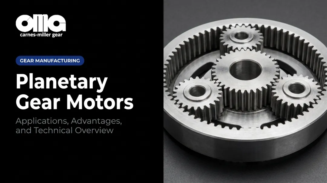
What Is a Planetary Gear System?
A planetary gear system (also called an epicyclic gear train, per ANSI/AGMA 6123 terminology) is a coaxial gear arrangement built around four members: a central sun gear, multiple planet gears, an outer ring gear (annulus), and a planet carrier.
The name "planetary" comes from the way planet gears orbit the sun gear while spinning on their own axes — mimicking the motion of planets around a star.
The configuration traces back to William Murdoch, who devised the sun-and-planet motion during the era of early steam engines — an attribution confirmed by both Britannica and the European Route of Industrial Heritage. The underlying geometry has remained structurally unchanged since then, because it solves a problem that no parallel-axis gear arrangement handles as efficiently.
Why Planetary Gears Beat Parallel-Axis Designs
The core mechanical advantage is load sharing. Because multiple planet gears engage simultaneously with both the sun gear and the ring gear, torque is distributed across several tooth mesh points at once. NASA's technical work on planetary gear dynamics confirms this translates to measurable weight and space savings versus parallel-shaft gear trains — and that advantage compounds in high-torque, space-constrained applications.
When designers need high torque output within a small radial envelope and a coaxial input/output alignment, planetary systems are the default solution. Parallel-axis reducers cannot match that combination without paying a steep penalty in size and weight.
Key Components of a Planetary Gear System
Sun Gear
Positioned at the center of the assembly, the sun gear receives input from the drive shaft and transmits power outward to the surrounding planet gears. Tooth count relative to the planet and ring gears directly sets the gear ratio and torque output — a smaller sun gear produces a higher reduction ratio; a larger one reduces it.
Planet Gears
Three or more planet gears are mounted on the carrier and mesh simultaneously with both the sun gear and the ring gear. This simultaneous multi-point contact is what makes planetary systems so load-capable — tooth stress is divided across every planet in the set, reducing wear and extending service life compared to single-mesh gear pairs.
Ring Gear (Annulus)
The outermost member of the assembly, the ring gear carries inward-facing internal teeth that mesh with the planet gears. Hold it stationary and you get the standard reduction output. Let it rotate — as in differential or multi-ratio configurations — and the same physical assembly can deliver multiple gear ratios without adding components.
Planet Carrier
The carrier is the structural frame that holds all planet gear shafts in precise angular alignment around the sun gear axis — and in a typical speed reducer, it serves as the output member. Carrier design is a critical performance factor:
- Built from hardened steel or aluminum alloy to maintain rigidity under load
- Must hold planet spacing within tight tolerances at all operating conditions
- Any misalignment directly causes unequal load distribution and accelerated tooth wear
Gear Tooth Geometry: Spur vs. Helical
| Feature | Spur Gears | Helical Gears |
|---|---|---|
| Helix angle | 0° | ~15–30° |
| Noise level | Moderate | Lower |
| Load capacity | Standard | Higher |
| Axial thrust | None | Present (requires bearing accommodation) |
| Manufacturing complexity | Lower | Higher |
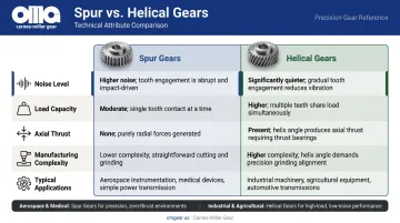
Helical gears are preferred when planetary sets must operate quietly or at higher torque densities — aerospace actuators and medical devices are typical examples. Spur gears remain the practical choice where simplicity and manufacturing cost matter more than noise reduction, which is why they dominate industrial and agricultural drives.
Common Types of Planetary Gear Configurations
Common Types of Planetary Gear Configurations
Single-Stage vs. Multi-Stage
| Single-Stage | Multi-Stage | |
|---|---|---|
| Structure | One sun, one planet set, one ring gear | Two or more planetary stages in series |
| Ratio Range | Up to ~10:1 (Neugart engineering guidance) | 9:1 to 100:1 overall |
| Typical Use | Servo drives, automation, moderate reductions | Wind turbines, industrial conveyors, heavy-duty hoists |
In a multi-stage unit, the output carrier of one stage drives the sun gear of the next — stacking ratios that a single stage can't reach on its own.
Shaft geometry adds another layer to configuration selection, since installation constraints often dictate which arrangement is viable.
Shaft Orientation Options
- In-line (coaxial): Input and output shafts share the same centerline — the most common configuration for servo and automation drives.
- Offset/parallel-shaft: Input and output are parallel but not coaxial, used in printing and material handling equipment.
- Right-angle: Input and output meet at 90° via integrated bevel or hypoid gears, used in conveyors and machine tools where space geometry demands a turn.
Specialized Configurations
- Harmonic drives (strain wave gears): Near-zero or zero backlash, high torsional rigidity — used in robotics, CNC axes, and surgical equipment where positioning repeatability is non-negotiable.
- Differential planetary sets: Allow two outputs to spin at independent speeds, used in automotive axle differentials.
- Simpson and Ravigneaux sets: Compound configurations that enable multiple forward and reverse ratios within a single housing — the National Academies identifies these as primary configurations in conventional automatic transmissions.
Essential Applications Across Industries
Automotive and Transportation
Most U.S. automatic transmissions use planetary gear sets, according to the National Academies, with Simpson, Ravigneaux, and Lapelletier configurations among the most common. Selective locking of the sun, ring, or carrier produces different reduction ratios without physically swapping gears.
Beyond conventional automatics, planetary gears are central to hybrid and EV drivetrains. Toyota's 2025 Crown Signia hybrid transaxle, for example, integrates two motor-generators with a single planetary gear and a reduction gear in a compact package. Forklifts, AGVs, and off-road construction equipment use wheel-drive planetary sets for their torque density and compact hub integration.
Industrial Machinery and Conveyors
Planetary gearboxes drive pumps, mixers, conveyors, and extruders where consistent torque under continuous duty matters. Their advantage over parallel-shaft reducers in industrial settings is vibration stability — distributing load across multiple planet meshes keeps vibration levels lower at high torque, reducing drive failures and maintenance frequency.
Aerospace, Defense, and Medical
These sectors impose the tightest manufacturing tolerances of any application. Aerospace actuators, satellite antenna positioning mechanisms, and defense equipment require minimal backlash and proven fatigue life. Medical devices, particularly surgical robots, depend on zero-backlash precision and quiet operation in environments that allow no margin for mechanical error.
Manufacturers serving these sectors must meet demanding AGMA accuracy standards. Carnes-Miller Gear achieves AGMA 13 ratings on ground spur gears and heat-treated gears — the tolerance level required for precision aerospace and medical components — at their 18,000-square-foot facility in Locust, NC.
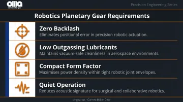
Robotics and Automation
Planetary designs represented just under 50% of precision gear products sold in 2022, with mobile robots projected to become the top industry for planetary precision gear demand by 2026. Harmonic drives in particular dominate robot joint applications because zero backlash directly determines end-effector positioning accuracy.
Cleanroom and vacuum environments add another requirement: gearboxes must operate without outgassing lubricants or generating contaminating particulates. That constraint narrows both material and lubrication choices considerably, making design selection as critical as the gear geometry itself.
Key design constraints for robotics applications include:
- Zero backlash — directly determines end-effector positioning accuracy
- Low outgassing lubricants — required for cleanroom and vacuum-rated systems
- Compact form factor — planetary sets fit inside joint housings where parallel-shaft reducers cannot
- Quiet operation — critical in collaborative robot environments near human operators
Energy, Mining, and Construction
NREL's baseline 750-kW wind turbine drivetrain model uses one planetary stage combined with two parallel stages to step rotor speed from ~22 rpm up to ~1,800 rpm, an overall ratio of around 81:1. That planetary first stage absorbs the massive, variable blade loads that would destroy a parallel-shaft input stage.
Mining and construction equipment rely on planetary wheel and track drives for the same reason: extreme torque in a hub-integrated package that survives shock loading and contamination. Rail traction systems use planetary reduction to manage the wide speed and torque range demanded by safe acceleration and braking cycles.
How Planetary Gears Are Manufactured
Gear Blank Preparation
Manufacturing begins with gear blanking — turning raw stock into a precisely dimensioned blank that establishes outer diameter, bore diameter, and face width before any teeth are cut. Blank accuracy matters because every subsequent operation references those surfaces. A blank with runout or dimensional variation propagates error through hobbing, shaping, heat treatment, and grinding.
Gear Tooth Cutting: Hobbing and Shaping
Two processes dominate gear tooth production for planetary components:
- Hobbing: A continuous, high-efficiency cutting process that works well for external teeth on sun gears and planet gears. The hob rotates in mesh with the blank, generating the tooth profile progressively.
- Shaping: The required method for internal ring gear teeth. As KHK confirms, standard hobbing machines cannot produce internal gears — a gear shaper with a pinion cutter is necessary. Shaping also handles external gears in tight clearance situations where hob runout would interfere.
Both processes establish pitch, pressure angle, and tooth profile — the parameters that determine how a gear meshes and how much load it can sustain. Carnes-Miller Gear achieves AGMA 10 ratings on shaped and hobbed gears through process discipline at this stage.
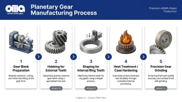
Heat Treatment
After tooth cutting, gear components are typically case-hardened (carburized) or through-hardened to build surface hardness and wear resistance while preserving a tough core. As ASM International notes, carburizing can cause geometric distortion severe enough to require post-treatment grinding. Precision manufacturers treat this distortion as a predictable outcome, leaving grinding stock on critical surfaces specifically to correct it downstream.
Gear Grinding for Precision Finishing
Grinding is the step that separates precision gears from commodity ones. It removes heat treat distortion, corrects tooth profile and lead errors, and brings geometry to final AGMA tolerances. Ground gears can achieve AGMA 13 ratings — required for aerospace, defense, and medical applications.
Those tolerances require the right equipment range. Carnes-Miller Gear offers gear grinding up to 400mm in diameter, covering most planetary gear components in demanding industrial and high-reliability sectors. Combined with in-house heat treatment and blanking, that capability supports true turn-key planetary component production.
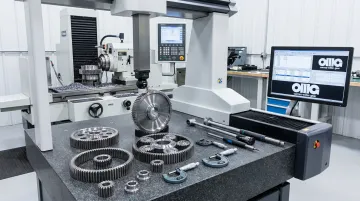
Inspection and Quality Standards
Finished components are inspected on gear measuring equipment that verifies:
- Tooth profile and lead accuracy
- Pitch and spacing uniformity
- Runout relative to the bore or reference diameter
Nital-etch testing is performed on hardened gears to detect grinding burns — thermal damage to the gear surface that weakens the case and creates a fatigue initiation site. Gear Technology cites ISO 14104 and AMS 2649D as the governing standards for this inspection. For aerospace and defense components, grinding burn is a disqualifying defect — Carnes-Miller Gear conducts nital-etch testing in-house to catch it before parts ever leave the facility.
Key Design and Performance Considerations
Gear Ratio Selection
The standard reduction ratio for a planetary set with the ring gear fixed is expressed as 1 + Nr/Ns, where Nr is the ring gear tooth count and Ns is the sun gear tooth count. Designers control the ratio by adjusting relative tooth counts while also weighing efficiency — each planetary stage introduces a small energy loss.
Multi-stage sets deliver higher ratios, but at the cost of added mechanical complexity and cumulative efficiency reduction. Getting the ratio right from the start is what makes load distribution manageable downstream.
Load Distribution and Balancing
Perfect load sharing among planets depends on:
- Precise manufacturing of all gear components
- Accurate carrier construction and assembly
- Consistent planet spacing
Even small carrier misalignments concentrate load on one or two planet gears, accelerating wear on those teeth. Adding more planets improves overall load capacity and torsional rigidity, but also raises the precision bar for the entire assembly — tighter tolerances on every component.
How that load gets managed over time, though, depends heavily on lubrication. Lubrication method selection is just as consequential as gear geometry.
Lubrication Methods
Three primary approaches apply to planetary gearboxes:
| Method | Best For | Notes |
|---|---|---|
| Grease | Low speed, intermittent duty | Simple, low maintenance |
| Oil splash (bath) | Moderate speed, enclosed housings | Standard for helical planetary sets |
| Forced oil (spray/mist) | High speed, continuous duty | Required where heat dissipation is critical |
Matching the lubrication method to operating speed, duty cycle, and gear type is a fundamental design decision. Wrong lubrication is one of the most common causes of premature planetary gearbox failure.
Frequently Asked Questions
What industries use planetary gears?
Automotive, aerospace, defense, medical, robotics, wind energy, industrial machinery, mining, construction, and rail all rely on planetary gears. The common thread is a need for high torque output within a compact envelope, reliable load distribution, and coaxial shaft alignment.
What is another name for a planetary gear?
Planetary gears are also called epicyclic gears or epicyclic gear trains. The term "epicyclic" refers to the circular path planet gears trace as they orbit the sun gear — a path that describes an epicycle in classical geometry.
What are the main components of a planetary gear system?
The four core components are the sun gear, planet gears, ring gear (annulus), and planet carrier. The sun gear drives the planets, which orbit inside the ring gear while the carrier holds them in position. Together, they transmit and multiply torque through simultaneous multi-point mesh contact.
What are the advantages of planetary gears over other gear types?
Key advantages include:
- High torque density within a compact radial footprint
- Even load distribution across multiple gear mesh points
- Coaxial input/output alignment
- High mechanical efficiency for the torque transmitted
No other gear architecture delivers all four of these properties at once — which is why planetary systems appear across so many demanding applications.
What is the difference between single-stage and multi-stage planetary gears?
A single-stage planetary set typically achieves up to 10:1 reduction. Multi-stage sets connect two or more planetary stages in series, with the output carrier of one stage driving the next sun gear. This arrangement reaches much higher overall ratios and greater torque output, at the cost of added length, weight, and complexity.