Hobbing and shaping produce accurate gear teeth, but heat treatment — the hardening process that gives gears their wear resistance — distorts what the cutter left behind. Grinding is what restores geometry to drawing tolerances while achieving surface finishes and precision levels that no pre-hardening process can match.
This article covers the full picture: how the CNC gear grinding process works, the key methods (form vs. generating), how precision is measured and verified, where ground gears are non-negotiable, and what innovations are reshaping the field.
Key Takeaways
- Post-heat-treatment gear grinding corrects thermal distortion and achieves tolerances unattainable before hardening
- Two primary methods exist: form (profile) grinding for flexibility, generating grinding for production speed
- Ground gears achieve significantly higher AGMA quality ratings than hobbed or shaped gears
- Nital-etch testing is the standard for detecting grinding burn in safety-critical applications
- CBN wheels can grind 2,200 to 2,500 parts per dress — far beyond what conventional abrasive wheels can sustain
What Is CNC Gear Grinding?
CNC gear grinding is a computer-controlled abrasive machining process used to finish gear teeth after cutting and heat treatment. Unlike hobbing or shaping, which remove large amounts of material to create the initial tooth form, grinding removes only small amounts (typically fractions of a millimeter) to bring tooth profiles to final dimensional tolerances and superior surface finish.
Why Grinding Comes Last
The key distinction is timing. Hobbing and shaping are soft-stage operations performed on unhardened steel. Heat treatment follows to harden the gear for wear resistance, but quenching and case-hardening introduce dimensional distortion that soft-stage cutting cannot anticipate or correct.
Grinding operates on the hardened part. That positioning allows it to:
- Correct thermal distortion from quenching and carburizing
- Achieve AGMA quality levels that unhardened machining cannot reach
- Produce tooth flank finishes in the Ra 0.1–0.3 micron range
- Hold tight involute profile tolerances across the full tooth face
The Role of CNC Control
Traditional gear grinding relied on mechanical lead cams and manual wheel positioning, a setup that was slow and heavily operator-dependent. CNC transforms this by coordinating multiple axes electronically, enabling capabilities that mechanical systems simply couldn't replicate consistently:
- Generates exact involute and helical profiles through synchronized motion
- Delivers repeatable results across high-volume production runs
- Eliminates repositioning errors inherent to manual setups
Reishauer, one of the pioneering names in generating gear grinding technology, has built continuous generating machines around this principle since 1945. Decades of refinement on that foundation is precisely why modern CNC generating grinders can hold AGMA 12–13 quality levels in production environments.
The CNC Gear Grinding Process Explained
Pre-Grinding Sequence
Before any grinding begins, the gear follows a defined preparation path:
- Gear blank preparation — The blank is turned, bored, and faced to drawing dimensions with grinding stock left on tooth flanks
- Rough tooth cutting — Hobbing or shaping generates the initial tooth form in soft material
- Heat treatment — Carburizing, quenching, and tempering harden the gear surface; this introduces distortion
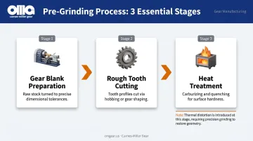
Research from Gear Solutions shows that even optimized heat treatment processes leave measurable distortion. Vacuum oil quenching, for example, can leave out-of-roundness in the range of 0.03–0.07 mm — values that grinding must correct before the part meets tolerance.
Fixturing and Setup
Precision arbors and centers hold the gear during grinding. Concentricity of the setup directly determines final gear accuracy — any movement of the workpiece translates immediately into tooth profile error, which means precise fixturing is what makes every downstream operation possible.
The Grinding Cycle
With the workpiece secured, the machine runs a structured sequence:
- Rough pass — Higher infeed removes the bulk of the grinding stock
- Semi-finish pass — Reduced infeed refines the profile
- Finish pass — Minimal infeed achieves final tolerance and surface finish
This progressive approach prevents thermal overload while efficiently removing distortion-affected material.
Wheel Dressing and Truing
The grinding wheel degrades during use in two ways: it loses its form, and its cutting surface becomes dull. Norton separates these into distinct operations — truing restores the wheel's geometry, while dressing exposes fresh abrasive grain and restores cutting sharpness.
For gear grinding specifically, dressing transfers the precise involute or thread profile into the wheel. Dressing triggers can be set by workpiece count, force indicators, finish degradation, or geometric drift — undressed wheels cause both profile errors and the thermal damage known as grinding burn.
Post-Grind Inspection
A ground gear isn't finished until it passes dimensional and metallurgical verification:
- Gear measuring centers verify tooth profile, lead, pitch, and runout
- Nital-etch testing detects grinding burn — subsurface thermal damage invisible to the naked eye
Carnes-Miller Gear performs in-house nital-etch testing as part of its quality protocol, governed by ISO 14104 and AMS2649 standards. This matters most for aerospace, defense, and medical customers where grinding burn would represent a latent failure mode in a safety-critical component.
Types of CNC Gear Grinding Methods
Form (Profile) Grinding
A disc wheel is dressed to the exact inverse of the tooth space profile and plunged into each tooth gap individually. The wheel's shape defines the resulting tooth geometry directly.
Best suited for:
- Large-module gears
- Internal gears with tight clearance constraints
- Custom or low-volume geometries
- Profiles that continuous generating equipment cannot access
Form grinding is slower per tooth than generating, but its geometric flexibility makes it the right choice when production volume is secondary to profile accuracy or access constraints. ### Generating Grinding
Where form grinding shapes each tooth individually, generating grinding works differently: the wheel and workpiece roll together in a conjugate motion that mathematically produces the involute profile — no dedicated wheel dressing to the tooth shape required, because the motion itself creates the form.
Advantages over form grinding:
- Faster cycle times — automotive transmission gears can run from 8 seconds for small pinions to roughly 1 minute for ring gears
- Consistent tooth geometry across all teeth in a batch
- Well-suited to high-volume spur and helical gear production
Reishauer's RZ 550, for example, handles grinding diameters from 5 to 550 mm and modules from 0.5 to 10 mm — a broad production range in a single machine platform.
External vs. Internal Gear Grinding
External gear grinding works with the wheel on the outside of the gear — clear access, good rigidity, well-established tooling. Internal gear grinding requires fitting a smaller wheel inside the gear bore, which creates challenges:
- Limited wheel diameter restricts rigidity
- Heat removal from an enclosed space is harder to manage
- Spindle clearance constrains the available tool options
Internal ring gear finishing after heat treatment ranks among the most demanding gear manufacturing applications — exactly because of these access and rigidity constraints.
Helical Gears and Complex Geometries
Helical gears require the workpiece to rotate and travel axially in synchronization during grinding — following the helix angle continuously. CNC electronic gearbox control handles this coordination without mechanical cams, which simplifies setup and allows flexible helix angle changes between jobs. Key demands this places on the machine:
- Tight axis synchronization throughout the full pass
- Consistent feed rate to avoid helix angle deviation
- Rapid re-configuration for different lead angles between batches
Worm gears and spiral bevel gears push the complexity further. These require multi-axis CNC platforms — Gleason's Phoenix, introduced as a 6-axis CNC hypoid cutting machine, shows how demanding the kinematics become for non-parallel-axis gear geometries.
Achieving Precision: Tolerances, Surface Finish, and Quality Standards
AGMA Quality Ratings
AGMA quality numbers define how tightly a gear's tooth profile, lead, pitch, and runout must conform to theoretical geometry. Higher numbers mean tighter tolerances. Tolerance values are not fixed universally — they're calculated from gear geometry per ANSI/AGMA 2015-1-A01 and the companion ISO 1328-1:2013 standard.
In practical terms:
| Process | Typical AGMA Quality | Application |
|---|---|---|
| Hobbing or shaping alone | AGMA 9–10 | General industrial |
| CNC gear grinding | AGMA 12–13+ | Aerospace, defense, precision drives |
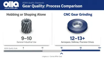
Carnes-Miller Gear achieves AGMA 13 on ground spur gears and heat-treated gears, compared to AGMA 10 on shaped and hobbed gears — a direct illustration of the quality step that grinding delivers.
Surface Finish Targets
Reishauer's research on polish grinding demonstrates that continuous generating gear grinding achieves approximately Ra 0.3 microns, with a subsequent polish-grinding stroke reducing this to approximately Ra 0.1 microns. Highly loaded aerospace and defense gears are typically specified to Ra < 0.1 micron.
Smoother flanks matter because tooth contact involves sliding motion. Lower surface roughness reduces friction, heat generation, and pitting fatigue — directly extending service life.
Grinding Burn Prevention
Hitting tight surface finish targets requires pushing the grinding process hard — but aggressive stock removal, dull wheels, or inadequate coolant delivery all generate excess heat at the grinding zone. If that heat exceeds the tempering temperature of the case-hardened surface, two failure modes result:
- Temper burn — Re-tempering softens the surface layer and creates residual tensile stress
- Rehardening burn: Re-austenitizing followed by rapid quenching creates a brittle white layer
Both are invisible without acid etching. Preventing either failure mode depends on process discipline at every stage of the grind cycle. Key controls include:
- Appropriate wheel specification (abrasive type, bond hardness, porosity)
- High-porosity vitrified bonds that allow coolant access and chip clearance
- Conservative infeed rates, especially during finish passes
- Consistent, well-directed coolant delivery
Nital-Etch Inspection
Nital etching applies a dilute nitric acid solution to ground tooth flanks. Heat-affected zones appear as dark stains against unaffected steel. ISO 14104 governs the test (surface temper etch inspection after grinding) and AMS2649 covers etch inspection of high-strength steel parts.
For aerospace, defense, and medical components, nital-etch is not optional — it's a contractual requirement. A gear that passes dimensional inspection while harboring grinding burn will fail in the field — and that failure traces directly back to the grinding process.
Industries and Applications of CNC Gear Grinding
The precision gearbox market was valued at $3.55 billion in 2025 and is projected to reach $7.86 billion by 2033, growing at 10.6% CAGR. Precision gear requirements are expanding across nearly every industrial sector, and ground gears sit at the center of that growth.
Where Ground Gears Are Non-Negotiable
- Aerospace and defense gearboxes — found in helicopters, actuation systems, and defense vehicles — operate under extreme load and vibration where tooth profile error directly compromises system reliability
- Surgical robotics and medical imaging equipment require smooth, near-silent motion; tooth flank roughness translates directly into positioning error and motion noise
- Mining and heavy industry applications run continuous, high-load cycles where maximum fatigue life at every tooth contact point is non-negotiable
EV Drivetrains and NVH Requirements
Electric vehicles have removed the masking noise of internal combustion engines, making gear whine audible at levels that would have been acceptable in a traditional drivetrain. Transmission error — the deviation between theoretical and actual gear rotation — is the root cause of gear whine, and it traces directly to tooth profile accuracy.
Reishauer's research on e-drive gear finishing confirms that EV gears require tighter tolerances and specific geometric modifications to manage NVH, and that grinding is the enabling process for controlling macro geometry, micro geometry, and surface structure simultaneously.
Aftermarket and Reverse-Engineered Gears
When industrial equipment goes out of production, the gears inside it don't stop wearing. Ground gears manufactured to reverse-engineered specifications — or improved versions of original drawings — extend machine service life across mining, agricultural, and rail sectors. Carnes-Miller Gear's reverse engineering capabilities serve exactly this need, producing replacement gears ground to original or better-than-original tolerances when drawings no longer exist.
Innovations Shaping the Future of CNC Gear Grinding
Multi-Axis Platforms and Integrated Dressing
Modern CNC gear grinders combine grinding and wheel dressing in a single setup. The machine dresses the wheel, returns to the workpiece, and continues grinding without operator intervention or repositioning. Reishauer's twin-spindle concept takes this further: one spindle grinds while the other loads or unloads, keeping the grinding zone active continuously and reducing non-productive time.
That continuous activity eliminates accumulated positioning error from manual setup changes, tightening process control and increasing throughput.
Closed-Loop In-Process Gauging
Traditional gear grinding relied on post-process measurement: grind the gear, take it to the inspection room, measure it, adjust the machine, repeat. Closed-loop systems change this by measuring tooth geometry during or immediately after the grind cycle and feeding corrections back to the CNC in real time.
Several major platform developers have brought this capability to production environments:
- Gleason HFC — delivers up to 100% quality inspection with automatic closed-loop corrections after each cycle
- Liebherr GDE — uses digital data exchange to link gear cutting machines directly to measuring instruments
- Reishauer closed-loop — applies corrections automatically to prevent misinterpretations and eliminate manual entry errors
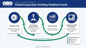
The practical effect is fewer scrapped parts and less reliance on operator judgment — both direct reductions in per-part cost for precision gear runs.
CBN Wheel Technology
Cubic boron nitride (CBN) abrasive is second only to diamond in hardness, making CBN wheels substantially more durable than conventional aluminum oxide wheels when grinding hard steels. Norton's data on CBN gear grinding shows CBN wheels lasting four to six months with 2,200 to 2,500 parts per dress — numbers that conventional wheels cannot approach.
3M specifies vitrified CBN wheels for powertrain grinding applications involving hardened steels between 55 and 70 HRC. The practical result is longer wheel life, better form retention between dressings, and higher material removal rates, each of which cuts per-part cost on high-volume runs.
Frequently Asked Questions
What is the process of gear grinding?
Gear grinding follows heat treatment. A CNC-controlled abrasive wheel finishes tooth profiles to final tolerances through rough, semi-finish, and finish passes. The process includes wheel dressing to maintain profile accuracy and concludes with dimensional inspection and nital-etch testing to verify no grinding burn occurred.
What are the different types of CNC grinding used for gears?
Form (profile) grinding uses a wheel dressed to the tooth space shape, plunging into each gap individually. It suits internal gears and custom profiles. Generating grinding rolls the wheel and gear together to produce the involute through conjugate motion, offering faster cycle times for high-volume spur and helical gear production.
What can cause a gear to grind (make grinding noise)?
Gear noise in service usually indicates worn or pitted flanks, loss of lubrication, excessive backlash, misalignment, or tooth profile error from manufacturing. This is distinct from gear grinding the manufacturing process, which is a deliberate precision finishing operation.
What AGMA quality levels can CNC gear grinding achieve?
CNC gear grinding can achieve AGMA quality levels of 12–13 or higher on precision spur and helical gears, compared to AGMA 9–10 typical for hobbed or shaped gears. The exact rating depends on machine capability, material, grinding process controls, and inspection method.
How does heat treatment distortion affect gear grinding?
Quenching and case-hardening cause dimensional changes and tooth profile distortion. Grinding is used specifically post-heat-treatment to restore geometry to drawing tolerances. Sufficient grinding stock must be left on tooth flanks during the cutting stage to accommodate distortion removal without undergrinding.
What materials are commonly CNC gear ground?
Through-hardened and case-hardened alloy steels (4140, 8620, and 9310) are the most common. CBN wheels are preferred for steels hardened above approximately 55–62 HRC, while conventional aluminum oxide wheels suit softer or lower-alloy steels where heat generation is less aggressive.