For OEM manufacturers and design engineers, helical and worm gears are the two most common candidates in high-reduction and industrial drive applications — and they're not interchangeable. The choice directly affects mechanical efficiency, operating temperatures, maintenance intervals, load capacity, and total lifecycle cost.
This guide cuts through the comparison systematically: what each gear type actually does, where each performs best, and how to make the right call for your specific application.
Key Takeaways
- Helical gears deliver 90–99%+ efficiency via rolling tooth contact — best for continuous-duty, high-torque applications
- Worm gears achieve high single-stage reduction (5:1 to 75:1 verified range) in a compact right-angle footprint — best for intermittent duty or self-locking requirements
- Worm gear efficiency falls with ratio: roughly 85% at 10:1, down to around 40% at 60:1
- Self-locking depends on lead angle and friction — not a guaranteed safety feature
- Total cost of ownership favors helical gears in high-hour applications despite higher initial cost
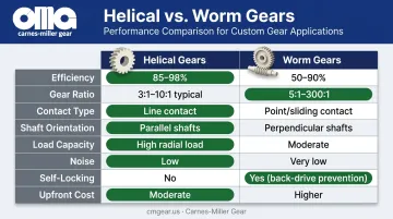
Helical vs Worm Gears: Quick Comparison
| Factor | Helical Gears | Worm Gears |
|---|---|---|
| Efficiency | 90–99%+ | 40–90% (ratio-dependent) |
| Gear ratio (single stage) | 1:1 to 10:1 | 5:1 to 75:1 |
| Contact type | Rolling/sliding | Predominantly sliding |
| Shaft orientation | Parallel | Right-angle |
| Load capacity | High — multiple teeth share load | Moderate — sliding limits torque density |
| Noise | Low — gradual engagement | Moderate — increases with wear |
| Self-locking | No | Conditional (low lead angle) |
| Upfront cost | Higher — tighter tolerances | Lower — simpler production |
Efficiency: The Core Trade-Off
KHK Gear lists helical gear efficiency at 90–99.5%, with parallel-axis gear trains reaching 98–99.5%. Worm gears range from 30–90% depending on design. That spread reflects how sharply efficiency drops as gear ratio climbs.
Oriental Motor's ratio-specific data puts worm efficiency at approximately 85% at 10:1 and 40% at 60:1. For continuous-duty applications running thousands of hours per year, that gap has direct dollar consequences.
Gear Ratio Range
Helical gears typically provide ratios from 1:1 to 10:1 per stage; higher reductions require multiple stages in series. Worm gears cover 5:1 to 75:1 in a single stage, with product families such as Boston Gear's 700 Series extending to 100:1.
What Are Helical Gears?
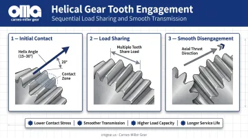
Helical gears are cylindrical gears with teeth cut at an angle — typically 15° to 30° — to the gear axis. Unlike spur gears, which engage with sudden full-face contact, helical teeth engage gradually as the gear rotates. At any moment, multiple teeth share the load simultaneously.
This progressive engagement is the source of helical gears' primary advantages:
- Lower stress per tooth — load distribution across multiple teeth reduces peak contact stress
- Smoother power transmission — gradual engagement eliminates the impact loading that causes noise and vibration in spur gears
- Higher load-carrying capacity — the helical overlap allows more torque for a given gear size
- Longer service life — reduced wear per tooth cycle extends maintenance intervals
The Axial Thrust Trade-Off
The helix angle that makes these gears efficient also generates axial thrust forces along the shaft. This load path must be managed with thrust bearings — an additional design requirement that adds cost and complexity to the drivetrain.
Double-helical (herringbone) gears solve this by pairing opposing helix angles, which cancel the axial thrust. The cost is manufacturing complexity: double-helical gears require tighter tolerances and more precise alignment.
Manufacturing Precision Requirements
Helical gears require precision hobbing or shaping followed by gear grinding to achieve the surface finish and tooth profile accuracy that deliver their efficiency advantage. ANSI/AGMA 2000-A88 covers quality levels Q3 through Q15 for spur and helical gears — higher Q numbers indicate tighter accuracy across tooth spacing, profile, lead, and runout.
Those upper quality tiers demand correspondingly capable equipment. Carnes-Miller Gear holds AGMA 13 on ground configurations and AGMA 10 on hobbed/shaped gears, with grinding capacity up to 400mm diameter — ratings that align directly with the accuracy requirements of industrial drive and motion control applications.
Where Helical Gears Are Used
Helical gears dominate continuous-duty, high-torque industrial machinery:
- Mining: ore processing conveyors, crushers, mills
- Steel manufacturing: rolling mills, wire rod mills
- Transportation: automotive transmissions, rail drivetrains
- Industrial machinery: mixers, compressors, centrifuges
The common thread is sustained output, where efficiency losses translate directly into energy cost and thermal management overhead.
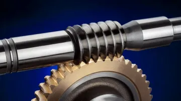
What Are Worm Gears?
A worm gear set consists of a cylindrical worm — essentially a screw thread — that meshes with a larger worm wheel. The worm must complete multiple full rotations to advance the wheel by a single revolution. This geometry enables very high single-stage reduction ratios in a compact, right-angle configuration.
The Self-Locking Condition
Worm gears can be self-locking — under the right conditions, the load cannot back-drive the input shaft. This happens when the worm's lead angle is smaller than the friction angle of the mating surfaces.
Machine Design gives a concrete example: a 5° lead angle with a static friction coefficient of 0.13 produces a friction angle of 7.4°, making the set statically self-locking. BJ-Gear places the practical threshold for reliable self-locking at a maximum helix angle of 5–6°.
Two important caveats engineers must understand:
- Self-locking is conditional, not guaranteed — friction changes with speed, vibration, temperature, and surface condition
- The same friction that resists back-driving is also what reduces efficiency — self-locking and high efficiency pull the design in opposite directions
Both conditions mean that safety-critical lifting and positioning systems should retain redundant braking — a nominal self-locking rating is not a substitute for a dedicated brake.
Efficiency Limitations
The sliding contact between worm and wheel — rather than the rolling contact in helical gears — generates significant friction and heat. KHK attributes cylindrical worm gear efficiency of 30–60% specifically to this sliding contact mechanism. At high ratios, thermal management becomes a real design constraint that affects housing selection, lubricant viscosity, and duty cycle limits.
Material Pairing
Worm gear sets typically pair a hardened or ground steel worm with a bronze worm wheel. This combination works because the bronze wheel's friction and wear characteristics are better suited to sliding-dominated mesh conditions than steel-on-steel contact.
Under overload or inadequate lubrication, the bronze wheel will wear faster than the steel worm. Lubrication maintenance is consequently more critical for worm gear sets than for helical applications.
Where Worm Gears Are Used
Worm gears are the practical choice when compact right-angle reduction or self-locking behavior matters more than peak efficiency:
- Material handling: hoists, elevators, escalators
- Valve actuation: Val-Matic documents worm gear actuators delivering output torque up to 180,000 ft-lbs with self-locking valve position maintenance
- Packaging machinery: intermittent conveyor indexing
- Food processing and agricultural equipment: space-constrained drives
- Automotive auxiliary systems: power windows, steering column adjusters
Helical vs Worm Gears: Which One Should You Choose?
The right choice comes down to five application parameters:
- Duty cycle — continuous vs. intermittent operation
- Required gear ratio — how much single-stage reduction is needed
- Shaft orientation — parallel vs. right-angle
- Efficiency and heat tolerance — what thermal envelope the drive must operate within
- Budget — initial cost vs. lifetime operating cost
Choose Helical Gears When:
- The application runs continuously or at high duty cycles
- Parallel shaft configuration is acceptable
- High torque at moderate to high speed is required
- Energy cost and thermal management are operational concerns
- Long maintenance intervals are a priority
Typical applications: mining conveyors, rolling mills, industrial compressors, heavy mixers, rail drives.
Choose Worm Gears When:
- Operation is intermittent or low-frequency
- A very high single-stage reduction ratio is needed in a compact footprint
- Right-angle drive geometry is required
- Self-locking or back-drive prevention has functional or safety value
- Low upfront cost takes priority over long-term energy savings
Typical applications: hoists, elevator drives, valve actuators, packaging line indexers.
The Total Cost of Ownership Calculation
Helical gears cost more to manufacture: tighter tolerances, precision hobbing, and grinding carry a real price premium. In continuous-duty service, though, that upfront cost often pays back quickly through lower energy consumption.
The DOE's motor systems efficiency framework shows that motor systems account for 60–70% of electricity consumed in an average plant. Consider the gap between a 95%-efficient helical drive and a 65%-efficient worm drive on a 100 hp continuous load running 8,760 hours per year at $0.05/kWh: that difference works out to roughly $15,000+ per year in additional energy cost for the less efficient drive.
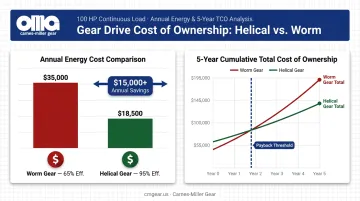
That gap scales with load, hours, and electricity rate. It's why worm gears are generally a poor fit for 24/7 industrial drives, regardless of their lower purchase price.
Real-World Application Examples
Helical Gears in Steel Rolling
A documented case from Brevini's work in Germany used 24 helical gearboxes in bar and wire rod mills processing various steel grades and superalloys. The selection rationale was modular design, customization capability, and the ability to handle sustained high-torque loads across different product grades — a profile that matches helical gearing's strengths directly. In a rolling mill running near-continuously, the efficiency advantage of helical over worm gearing would compound into significant annual energy savings.
Worm Gears in Valve Actuation
Val-Matic's worm gear actuators serve plug, ball, and butterfly valve applications with output torque capacity up to 180,000 ft-lbs. The self-locking behavior is the point: the actuator holds valve position without a separate brake motor, and the compact right-angle form factor fits standard valve mounting configurations. In this application, the efficiency trade-off is irrelevant — the drive operates briefly and intermittently, and the self-locking feature delivers direct functional value that no helical gear set can replicate.
How Application Context Drives Gear Selection
Both examples above hinge on the same four parameters: duty cycle, ratio requirement, shaft orientation, and load type. Those parameters push toward helical in a continuously running mill and toward worm in an intermittent valve actuator. Engineers who skip that analysis and select on purchase price alone frequently end up retrofitting equipment within two to three years.
When application requirements are defined and tolerances matter, Carnes-Miller Gear manufactures both helical and worm gears to customer specifications, with grinding to AGMA 13 and hobbing/shaping to AGMA 10, up to 400mm diameter. Reach out to CMG at dan@cmgear.us or 704-888-4448 to discuss your specific application.
Conclusion
Helical gears are the stronger performer on efficiency, load capacity, and service life for demanding, continuous-duty applications. Worm gears are the pragmatic choice when compact right-angle reduction, self-locking behavior, or low initial cost are the dominant requirements.
Neither type is universally superior. For OEM manufacturers and plant engineers, getting the selection right from the start prevents costly retrofits, avoids unplanned downtime from thermal failure or premature wear, and directly impacts total operating cost over the machine's service life. If your application sits at the boundary — high reduction ratios with moderate efficiency demands, or right-angle drives that also need reasonable power throughput — a custom-manufactured gear set built to your exact load and geometry requirements will consistently outperform an off-the-shelf compromise. That's where precision job shops like Carnes-Miller Gear provide the most direct value.
Frequently Asked Questions
Which is better: helical gear or worm gear?
Neither is universally better. Helical gears outperform on efficiency and continuous-duty load capacity; worm gears win on compact high-ratio reduction and conditional self-locking. The right choice depends entirely on duty cycle, shaft orientation, required ratio, and whether energy cost or upfront cost is the dominant constraint.
What are the main disadvantages of worm gears?
The primary drawbacks are lower mechanical efficiency (especially at high ratios due to sliding contact), higher heat generation requiring more frequent lubrication, and lower torque-carrying capacity relative to size. These limitations make worm gears a poor fit for continuous, high-power applications.
Can worm gears be back-driven?
Worm gears with a lead angle below 5–6° are self-locking, meaning the load cannot back-drive the worm. Higher lead angle designs may allow back-driving, and even nominally self-locking sets can slip under vibration or changing friction conditions. Always verify the self-locking condition for safety-critical applications.
What efficiency can I expect from helical gears vs worm gears?
Helical gears typically achieve 90–99%+ mechanical efficiency due to their rolling contact geometry. Worm gear efficiency varies significantly with ratio — approximately 85% at 10:1, dropping to around 40% at 60:1. Broader technical references place the full worm gear range at 30–90% depending on design, ratio, and lubrication.
What gear ratio ranges are typical for helical vs worm gears?
Helical gears provide ratios from 1:1 to 10:1 per stage; multiple stages are required for higher reductions, adding complexity. Worm gears achieve 5:1 to 75:1 in a single compact stage (with some product families extending to 100:1), making them far more practical when high single-stage reduction is the requirement.
How does tooth geometry affect heat generation and wear?
Helical gear teeth engage through predominantly rolling contact, keeping friction and heat generation low. Worm gear teeth slide throughout mesh, generating significantly more heat. Proper material pairing (hardened steel worm with bronze wheel) and consistent lubrication are critical to managing wear and avoiding premature failure.