Yet engineers and procurement teams often specify helical gears based on surface-level familiarity: "they're quiet, they handle high loads." That shorthand works until it doesn't — until a helix angle is misjudged, bearings fail prematurely from unaccounted axial thrust, or the wrong gear type gets selected entirely.
This guide covers what helical cut gears actually are, the mechanics behind how they work, their real advantages and trade-offs, how they're manufactured, and where they belong.
Key Takeaways
- Helical gear teeth are cut at an angle to the rotation axis, creating gradual progressive tooth engagement rather than sudden full-face contact
- This angled engagement raises the contact ratio, distributes load across multiple teeth simultaneously, and reduces noise and vibration
- The same geometry generates axial thrust along the shaft, which must be managed through thrust bearings or a double helical (herringbone) configuration
- Helical gears are the standard for high-speed, high-torque, and noise-sensitive applications across automotive, industrial, aerospace, and medical sectors
- Manufacturing precision, including hobbing and post-heat-treatment grinding, determines whether rated performance is actually achieved
What Are Helical Cut Gears?
Helical cut gears are cylindrical gears whose teeth are machined at a helix angle relative to the gear's rotational axis. Rather than running straight across the face width, each tooth follows a helical path around the gear body.
That distinction matters mechanically. KHK defines helical gears as cylindrical gears with slanted tooth traces used for smooth transmission with less vibration than spur gears — and the slant is the entire reason for that performance difference.
How They Differ From Other Gear Types
Helical gears are frequently confused with or compared to spur gears, but the distinction is fundamental:
- Spur gears have teeth that run parallel to the rotational axis and contact the mating gear simultaneously across the full tooth face, creating impact loading
- Helical gears have angled teeth that engage progressively, point by point across the face width
- Bevel and worm gears operate on non-parallel shaft geometries entirely, placing them in a separate design category altogether
Helical gears are designed for parallel-shaft applications. Crossed helical gears (sometimes called screw gears) extend that capability to non-parallel, non-intersecting shafts, though they carry lower load capacity and generate higher sliding friction — making them a distinct subtype rather than a direct substitute.
Single vs. Double Helical Configurations
There are two primary configurations:
- Single helical : the standard form, with teeth cut in one helix direction. This configuration produces axial thrust that must be managed in the bearing and housing design.
- Double helical (herringbone) : two opposing helix directions on one gear body. The axial forces from each half cancel out, eliminating net shaft thrust. This configuration is used when axial load management is a hard design constraint.
For parallel-shaft applications demanding high contact ratio, load capacity, and quiet operation, helical gears remain the go-to configuration — especially when manufactured to tight AGMA quality grades.
How Do Helical Cut Gears Work?
Helical gear operation follows a defined mechanical sequence from initial tooth engagement through full load transfer. Each stage directly shapes the performance characteristics that distinguish helical gears from simpler designs.
Tooth Engagement: How Contact Begins
With spur gears, the entire tooth face contacts the mating gear simultaneously. That sudden full-face contact creates a shock load — the mechanical source of spur gear noise and vibration.
Helical gear teeth behave differently. Contact begins at one edge of the tooth face and sweeps progressively across the full face width as rotation continues. The load builds gradually rather than arriving all at once.
The helix angle controls how quickly this sweep occurs. A larger helix angle increases the overlap of successive tooth engagements, extending contact duration and further smoothing load transfer. A smaller helix angle reduces overlap and approaches spur gear behavior.
Contact Ratio and Load Distribution
The gradual engagement of helical teeth means more than one tooth pair is in contact at any given moment. This is the contact ratio — a measure of how many tooth pairs share the load simultaneously.
According to Gear Solutions, standard gears typically have contact ratios of 1.2 to 1.6. Helical gears increase total contact ratio by adding an overlap ratio (from the axial tooth engagement) on top of the transverse contact ratio. A 1983 NASA study on aircraft gear systems confirms that gears with contact ratios above 2.0 share load across two or three teeth simultaneously, reducing the load each tooth carries.
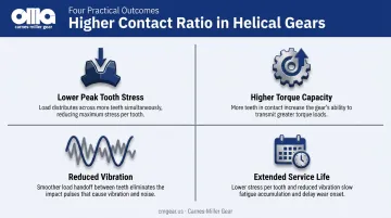
The practical outcomes of higher contact ratio:
- Lower peak tooth stress at any given load
- Higher torque capacity within the same gear diameter
- Reduced vibration from more consistent load transfer
- Extended service life under continuous-duty, high-cycle conditions
Axial Thrust: The Mechanical Trade-Off
The same angled geometry that produces gradual engagement also generates a force component along the shaft axis. Because the tooth helix pushes against the mating gear at an angle, the reaction force splits into a radial component (useful rotation) and an axial component (thrust along the shaft).
KHK's gear force analysis confirms the relationship: axial force scales with the tangent of the helix angle (Fa = Ft × tan β). A larger helix angle means more axial thrust.
This axial thrust must be absorbed by thrust bearings or bearing arrangements designed to handle combined radial and axial loads. Common solutions include Timken tapered roller bearings and NSK double-direction thrust ball bearings.
Failure to account for axial thrust in the bearing and housing design is a consistent cause of premature bearing failure in helical gear systems.
The double helical (herringbone) configuration solves the problem structurally — opposing helix directions cancel the axial forces, so the shaft sees no net thrust.
What Helical Gears Deliver
The result of progressive engagement, high contact ratio, and distributed loading is smooth, continuous torque transfer at high rotational speeds, with low vibration and low acoustic emission.
In downstream systems like gearboxes, drive trains, and precision actuators, that output consistency matters. Vibration from a gear mesh transmits into surrounding components — reducing it at the source protects bearings, housings, and the driven equipment.
Key Advantages — and One Critical Trade-Off
Quieter Operation
Gradual tooth engagement eliminates the impact loading that causes spur gear noise. Helical gears are the standard wherever acoustic performance is regulated or operationally critical because reduced vibration directly decreases fatigue loading on surrounding components, extending service intervals beyond the gear itself.
Higher Load Capacity
The elevated contact ratio distributes force across multiple teeth at once, allowing helical gears to transmit substantially more torque for the same gear diameter compared to spur gears. This is why they dominate in high-torque industrial and automotive applications where size and weight matter.
Longer Service Life
Distributed load reduces peak Hertzian contact stress (surface pressure at the contact point) on individual tooth surfaces, which reduces wear rate and delays fatigue crack initiation. In high-cycle applications, properly specified helical gears consistently outlast spur gears under equivalent loading — a meaningful advantage in aerospace, defense, and heavy industrial service where replacement downtime is costly.
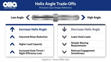
Design Flexibility via Helix Angle
The helix angle is a tunable parameter, not a fixed value:
- Increase it → improved noise reduction and load capacity, but higher axial thrust and a small efficiency penalty
- Reduce it → lower axial loads, simpler bearing requirements, but less smoothness
This adjustability makes helical gears adaptable across a wide range of performance requirements from the same basic gear geometry.
The Trade-Off: Efficiency and Axial Thrust
Helical gears are marginally less efficient than spur gears because the sliding contact component along the tooth helix introduces friction losses. KHK's gear efficiency data lists both spur and helical gears at 98.0–99.5% efficiency under ordinary operating conditions — narrow enough that lubrication quality and geometry tolerances often matter more than gear type itself.
Axial thrust adds real system complexity. Thrust bearings cost more and introduce additional failure modes if undersized or misspecified. For racing applications or extreme-efficiency scenarios, that trade-off may favor spur gears. In most industrial contexts, though, the load capacity and fatigue life gains make helical gears the practical default — the bearing overhead is a known, manageable cost.
How Helical Cut Gears Are Manufactured
Cutting: Hobbing and Shaping
Helical gear teeth are cut by two primary processes:
- Gear hobbing — a continuous generating process where a helical hob cutter machines teeth progressively around the gear blank. The hob feeds across the face width while the workpiece rotates in a synchronized ratio that produces the specified helix angle. It's the workhorse process for most helical gear production.
- Gear shaping — uses a reciprocating cutter, better suited for gears with limited runout clearance or internal gear configurations where hob overrun isn't possible.
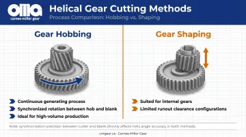
Both processes require precise synchronization between workpiece rotation and cutter motion. Deviations in that synchronization translate directly into helix angle errors — and helix angle errors affect noise, contact pattern, and load distribution in the final gear.
Heat Treatment and Grinding
After cutting, most helical gears used in demanding applications are heat treated to harden tooth surfaces for wear resistance. The problem: KHK notes that carburizing and induction hardening can cause geometric distortion, with carburizing potentially reducing gear accuracy by approximately one grade.
Gear grinding after heat treatment corrects that distortion, restoring precise tooth geometry and surface finish. For critical applications, it's often the difference between a gear that meets print and one that doesn't survive qualification.
AGMA quality grades define the tolerance standards. Per Gear Solutions' summary of ANSI/AGMA 2015-1-A01, the standard uses accuracy grades A2 through A11, with lower numbers representing tighter tolerances. High-accuracy grades (A2–A5) require precision grinding; medium grades (A6–A9) may be achievable with quality hobbing; lower grades (A10–A11) are less demanding.
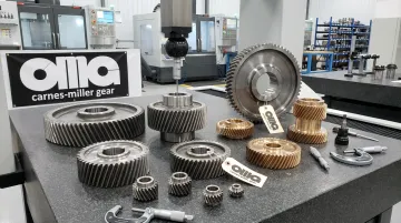
Carnes-Miller Gear's Capabilities
Carnes-Miller Gear runs the full manufacturing sequence in-house: hobbing, shaping, and gear grinding. Hobbed and shaped gears reach AGMA 10; ground gears reach AGMA 13, with grinding capacity up to 400mm in diameter.
That range covers applications from industrial gearboxes through aerospace and defense systems. Carnes-Miller also performs in-house nital-etch testing on ground gears to catch grinding burns before parts ship.
Where Helical Cut Gears Are Used
Helical gears perform best — and are therefore preferred — under these conditions:
- High rotational speeds where spur gear impact loading becomes acoustically and mechanically unacceptable
- Continuous-duty or high-cycle applications where contact ratio's effect on wear life is significant
- High-torque requirements in compact envelopes
- Noise-sensitive environments including industrial facilities, transportation systems, and medical devices
Key Industries
| Industry | Primary Applications |
|---|---|
| Automotive & Transportation | Manual transmission forward gear pairs; helical engagement chosen over spur specifically for smoother, quieter contact during forward operation |
| Industrial Machinery & Mining | Parallel-shaft gearboxes for conveyors, mills, crushers, and pumps — applications where torque density and long service life justify the design |
| Aerospace & Defense | Precision actuators, wing flap systems, cockpit instrumentation, and auxiliary power units requiring reliable, low-noise operation |
| Medical Equipment | Surgical tools and imaging systems where quiet operation and precise positioning are hard requirements |
Where Helical Gears Are Not the Right Choice
Simple, low-speed, cost-sensitive applications often favor spur gears: higher efficiency, lower manufacturing cost, and no thrust bearing requirement. Gear selection should always be driven by specific performance requirements, and helical gears are better suited to demanding operating conditions rather than universally superior.
Frequently Asked Questions
What are helical cut gears?
Helical cut gears are cylindrical gears with teeth machined at a helix angle to the rotational axis. This angled tooth form creates gradual, progressive tooth engagement rather than simultaneous full-face contact, which is the mechanical basis for their quiet operation and high load capacity.
What are the advantages of helical cut gears?
Helical gears offer four core advantages: quieter operation from gradual tooth engagement, higher load capacity from the elevated contact ratio, longer service life from distributed tooth stress, and design flexibility through helix angle selection. The trade-off is axial thrust generation, which requires thrust bearings to manage.
What is the helix angle, and how does it affect performance?
The helix angle is the angle between the gear tooth and the gear's rotational axis. Increasing it improves noise reduction and load distribution but raises axial thrust and marginally reduces efficiency. Selecting the right helix angle requires balancing these competing factors for the specific application.
What is the difference between helical gears and spur gears?
Spur gears have straight teeth parallel to the axis that contact simultaneously across the full face, generating impact loads and noise. Helical gears have angled teeth that engage progressively, producing quieter operation and higher load capacity, but also generating axial thrust that spur gears don't.
What is a double helical (herringbone) gear?
A double helical gear combines two opposing helix directions on a single gear body. The axial thrust forces from each half cancel each other out, delivering the smooth operation and high load capacity of helical gears without the axial thrust management challenge.
Can helical gears be used on non-parallel shafts?
Standard helical gears are designed for parallel shafts. Crossed helical gears can transmit motion between non-parallel, non-intersecting shafts, but at the cost of lower load capacity and higher sliding friction. For non-parallel shaft applications, bevel or worm gears are the better choice.
Conclusion
Every performance characteristic of helical cut gears traces back to one geometric feature: the helix angle that causes teeth to engage progressively rather than all at once. Quieter operation, higher load capacity, and extended service life all follow directly from that angled tooth form and the higher contact ratio it produces.
Understanding that connection lets engineers do more than select a gear type. It lets them choose the right helix angle, predict axial thrust loads, specify the correct bearing arrangement, and set the appropriate AGMA quality grade for the application — rather than treating helical gears as a black box.
Proper specification also requires that manufacturing delivers on paper tolerances. Hobbing produces the tooth geometry; grinding after heat treatment restores the precision that hardening distorts.
Teams sourcing precision helical gears for aerospace, defense, medical, or industrial applications benefit from working with a manufacturer who can execute both steps in-house and verify the result. Carnes-Miller Gear has been doing exactly that since 1973 — contact the team to discuss your helical gear requirements.